Closed loop additive injection and monitoring system for oilfield operations

a monitoring system and closed-loop technology, applied in the field of oilfield operations, can solve the problems of reducing hydrocarbon production, requiring expensive rework operations or even abandoning the wellbore, and reducing the life of the wellbore itsel

Inactive Publication Date: 2005-02-08
BAKER HUGHES INC
View PDF53 Cites 119 Cited by
  • Summary
  • Abstract
  • Description
  • Claims
  • Application Information

AI Technical Summary

Benefits of technology

The wellsite controller is preferably a microprocessor-based system and can be programmed to adjust the flow rate automatically when the calculated flow rate is outside predetermined limits provided to the controller. The flow rate is increased when it falls below a lower limit and is decreased when it exceeds an upper limit. Also an embodiment of the present invention is a system wherein the controller can also switch between redundant pumps when the flow rate cannot be controlled with the pump then in-service.
The system of the present invention may be configured for multiple wells at a wellsite, such as an offshore platform. In one embodiment, such a system includes a separate pump, a fluid line and an onsite controller for each well. Alternatively, a suitable common onsite controller may be provided to communicate with and to control multiple wellsite pumps via addressable signaling. A separate flow meter for each pump provides signals representative of the flow rate for its associated pump to the onsite common controller. The onsite controller may be programmed to display the flow rates in any order as well as other relevant information. The onsite controller at least periodically polls each flow meter and performs the above-described functions. The common onsite controller transmits the flow rates and other relevant or desired information for each pump to a remote controller. The common onsite controller controls the operation of each pump in accordance with the stored parameters for each such pump and in response to instructions received from the remote controller. If a common additive is used for a number of wells, a single additive source may be used. A single or common pump may also be used with a separate control valve in each supply line that is controlled by the controller to adjust their respective flow rates.
A suitable precision low-flow, flow meter is utilized to make precise measurements of the flow rate of the injected additive. Any positive displacement-type flow meter, including a rotating flow meter, may also be used. The onsite controller is environmentally sealed and can operate over a wide temperature range. The present system is adapted to port to a variety of software and communications protocols and may be-retrofitted on the commonly used manual systems, existing process control systems, or through uniquely developed additive management systems developed independently or concurrently.
The additive injection of the present invention may also utilize a mixer wherein dif

Problems solved by technology

Insufficient amounts of treatment additives can increase the formation of corrosion, scale, paraffins, emulsion, hydrates etc., thereby reducing hydrocarbon production, the operating life of the wellbore equipment and the life of the wellbore itself,

Method used


Image

  • Closed loop additive injection and monitoring system for oilfield operations
  • Closed loop additive injection and monitoring system for oilfield operations
  • Closed loop additive injection and monitoring system for oilfield operations

Examples


Embodiment Construction

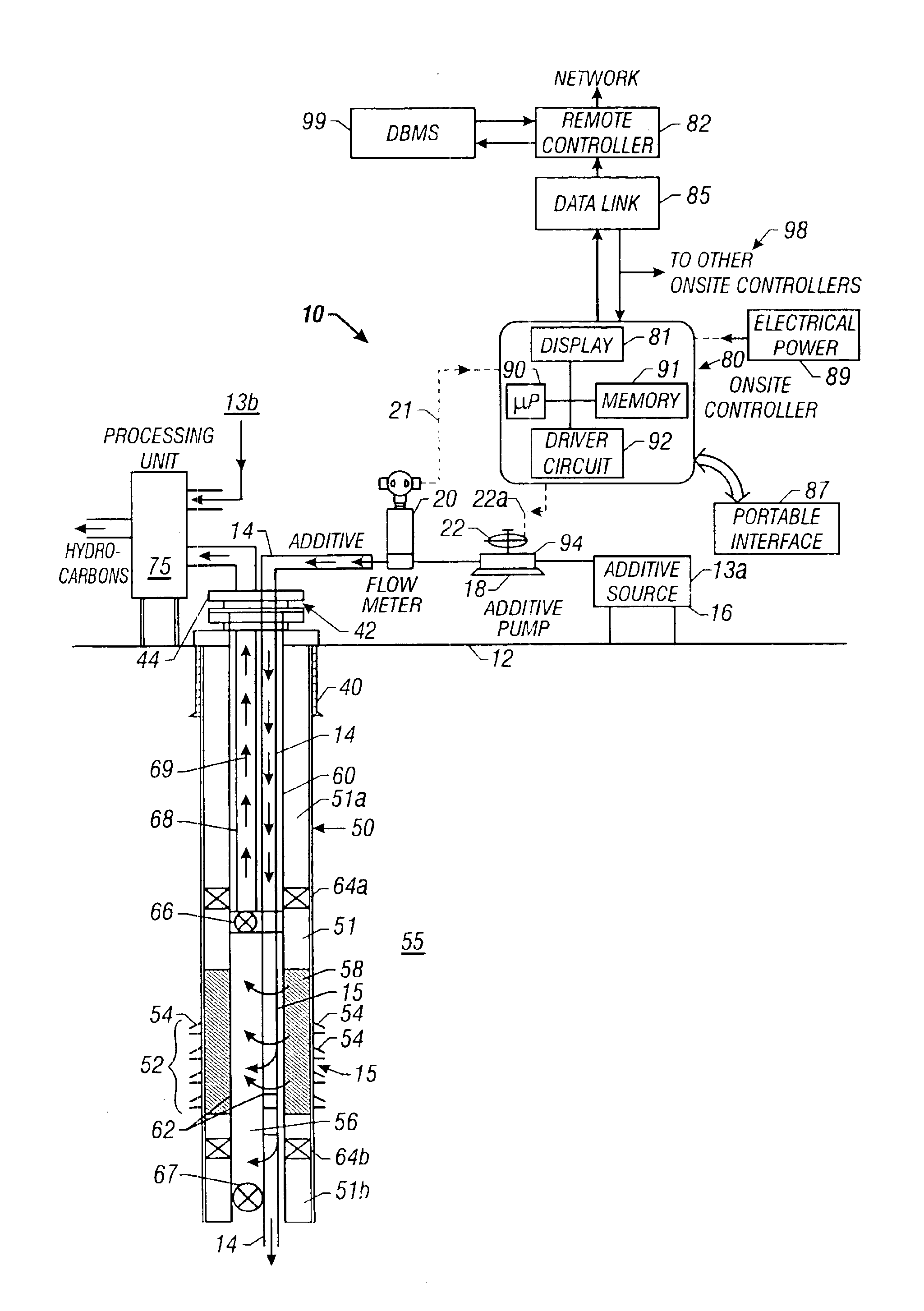
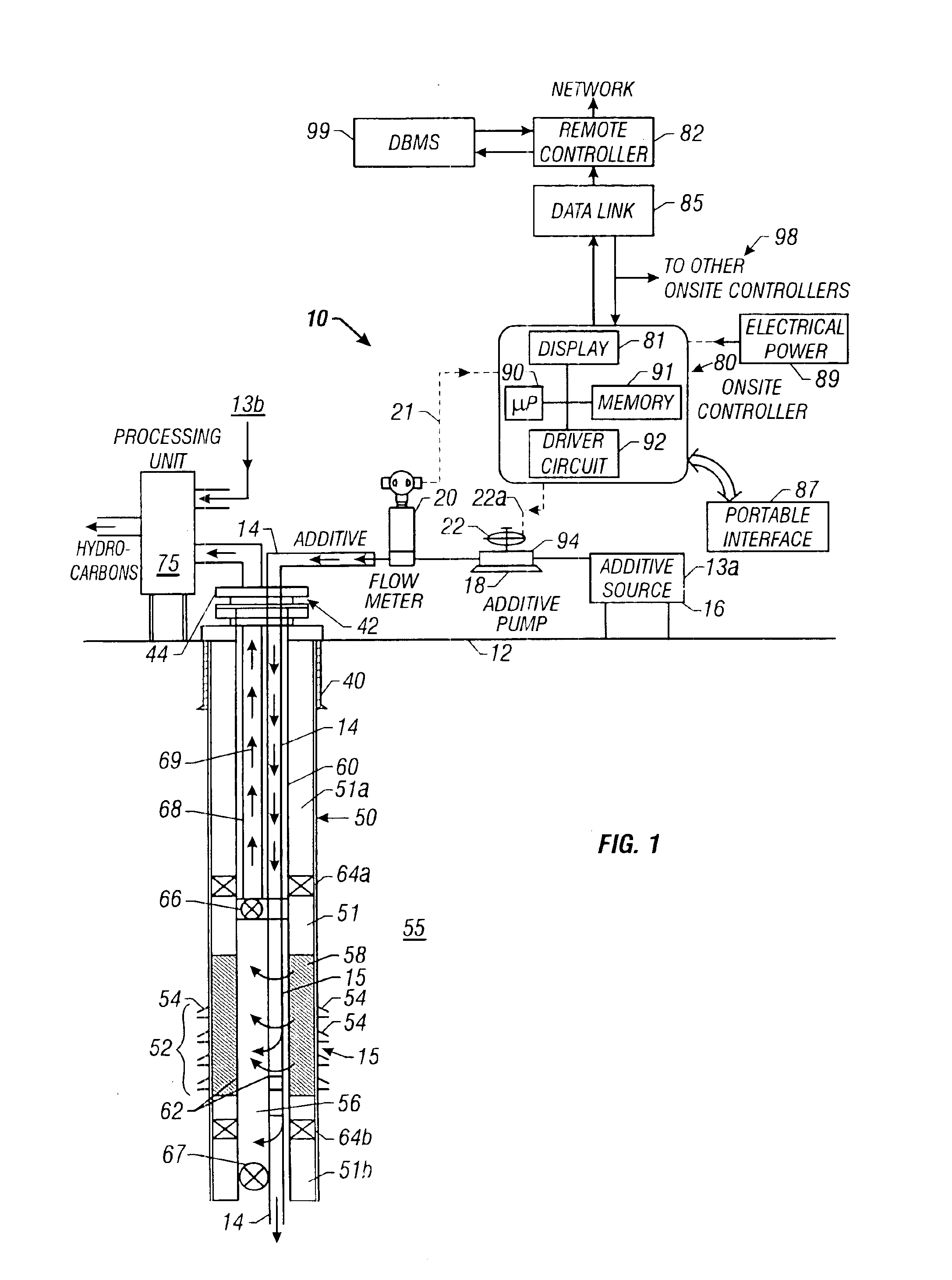
FIG. 1 is a schematic diagram of a wellsite additive injection system 10 according to one embodiment of the present invention. The system 10, in one aspect, is shown as injecting and monitoring of additives 13a into a wellbore 50 and, in another aspect, injecting and monitoring of additives 13b into a wellsite surface treatment or processing unit 75. The wellbore 50 is shown to be a production well using typical completion equipment. The wellbore 50 has a production zone 52 which includes multiple perforations 54 through the formation 55. Formation fluid 56 enters a production tubing 60 in the well 50 via perforations 54 and passages 62. A screen 58 in the annulus 51 between the production tubing 60 and the formation 55 prevents the flow of solids into the production tubing 60 and also reduces the velocity of the formation fluid entering into the production tubing 60 to acceptable levels. An upper packer 64a above the perforations 54 and a lower packer 64b in the annulus 51 respecti...


PUM


Abstract

A system is provided that monitors at the wellsite injection of additives into formation fluids recovered through wellbores and controls the supply of such additives from remote locations. A pump supplies the selected additive from a source at the wellsite into the wellbore via a suitable supply line. A flow meter in the supply line measures the flow rate of the additive through the supply line and generates signals representative of the flow rate. A controller at the wellsite determines the flow rate from the flow meter signals and in response thereto controls the pump to control the flow rate of the additive to the well. The wellsite controller interfaces with a suitable two-way communication link and transmits signals and data representative of the flow rate, and other parameters to a second remote controller. The remote controller transmits command signals to the wellsite controller representative of any change desired for the flow rate. The wellsite controller is microprocessor based and may be programmed at the wellsite or by the remote controller to adjust the flow rate. The system of the present invention may be configured for multiple wells, with each well having a separate wellsite controller or a common wellsite controller.

Description

BACKGROUND OF THE INVENTION1. Field of the InventionThis invention relates generally to oilfield operations and more particularly to a remotely / network-controlled additive injection system for injecting precise amounts of additives or chemicals into wellbores, wellsite hydrocarbon processing units, pipelines, and chemical processing units.2. Background of the ArtA variety of chemicals (also referred to herein as “additives”) are often introduced into producing wells, wellsite hydrocarbon processing units, oil and gas pipelines and chemical processing units to control, among other things, corrosion, scale, paraffin, emulsion, hydrates, hydrogen sulfide, asphaltenes and formation of other harmful chemicals. In oilfield production wells, additives are usually injected through a tubing (also referred to herein as “conductor line”) that is run from the surface to a known depth. Additives are introduced in connection with electrical submersible pumps (as shown for example in U.S. Pat. No....

Claims


Application Information

Patent Timeline
IPC IPC(8): E21B37/06E21B37/00E21B41/02E21B43/25E21B41/00
CPCE21B37/06E21B43/25E21B41/02Y10T137/0391Y10T137/7759Y10T137/7761
Inventor KOHL, KRISTOPHER T.MEANS, C. MITCH
Owner BAKER HUGHES INC
Why Eureka
Try Eureka