Circle structure of motor grader

Inactive Publication Date: 2005-02-08
KOMATSU LTD
View PDF7 Cites 11 Cited by
  • Summary
  • Abstract
  • Description
  • Claims
  • Application Information

AI Technical Summary

Benefits of technology

According to the above constitution, the circle gear is made the integrated ring-shaped circle gear, and therefore it is sufficient if only the circle gear is mounted with the position of a worn or broken portion being displaced as compared with the divided circle gear. Due to this, it is not necessary to replace the ring gear, replacement cost does not occur, and therefore maintenance cost becomes low. By providing the integrated ring-shaped circle gear, the load applied to the teeth of the circle gear can be received by the entire circle gear, and therefore rigidity becomes high with less deformation as compared with the divided circle gear, thus improving durability.
Since the circle mounting bolts are placed at the equal pitches on the mounting pitch circle, the circle gear can be mounted to the circle by rotationally moving it by one pitch at each time, and therefore assembly is facilitated. When the circle gear is mounted with the position of a worn or broken portion of the circle gear being displaced, the circle gear can be mounted to the circle only by rotat

Problems solved by technology

When the circle gear is mounted with the position of a worn or broken portion of the circle gear being displaced, the circle gear can be mounted to the circle only by rotationally moving it

Method used


Image

  • Circle structure of motor grader
  • Circle structure of motor grader
  • Circle structure of motor grader

Examples


Embodiment Construction

A preferred embodiment of a circle structure of a motor grader according to the present invention will be explained below with reference to the drawings.

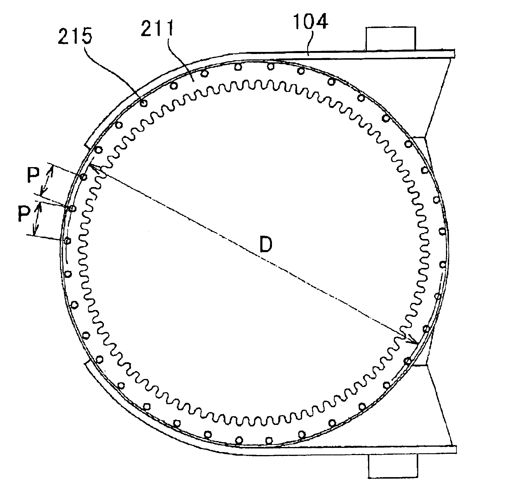
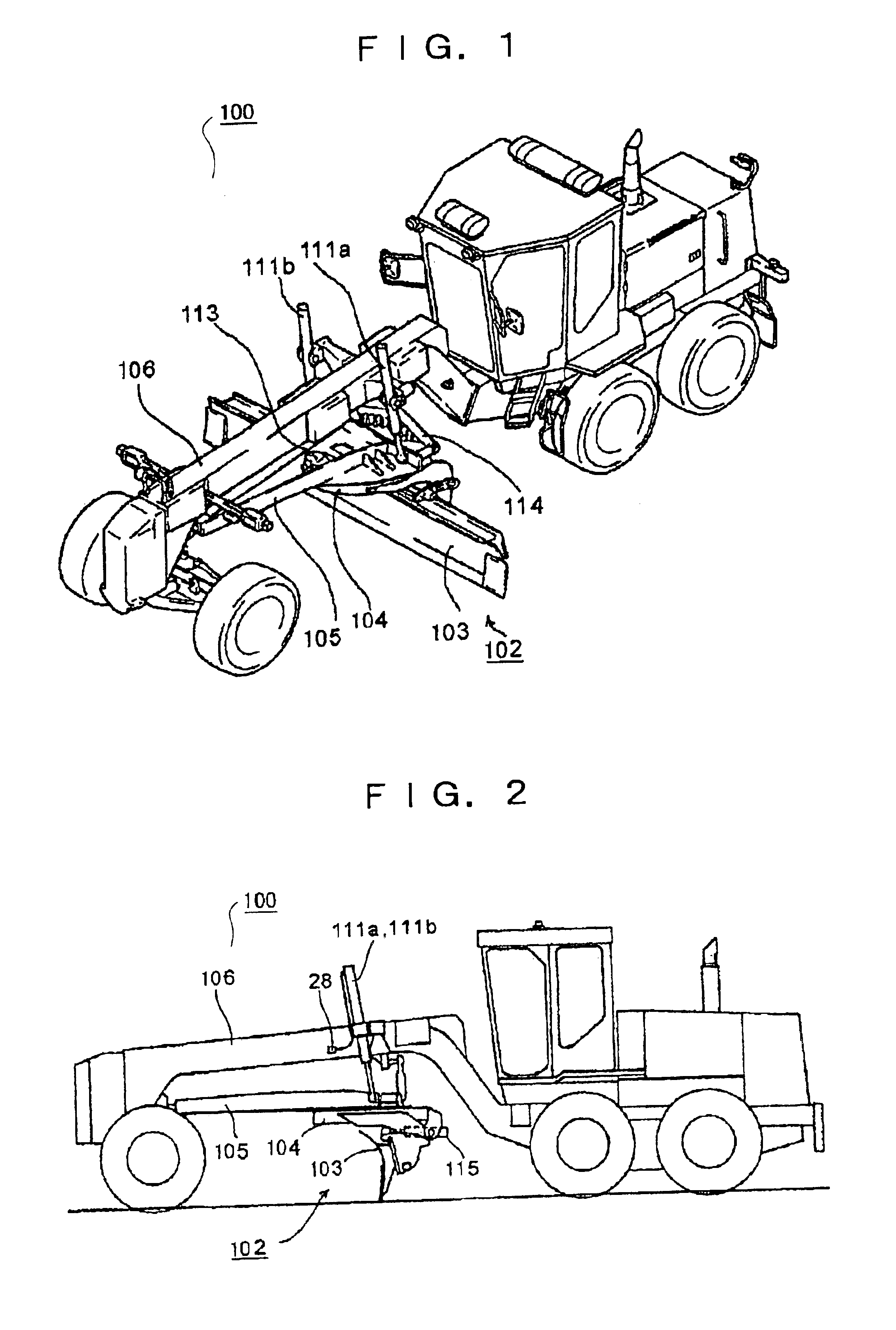
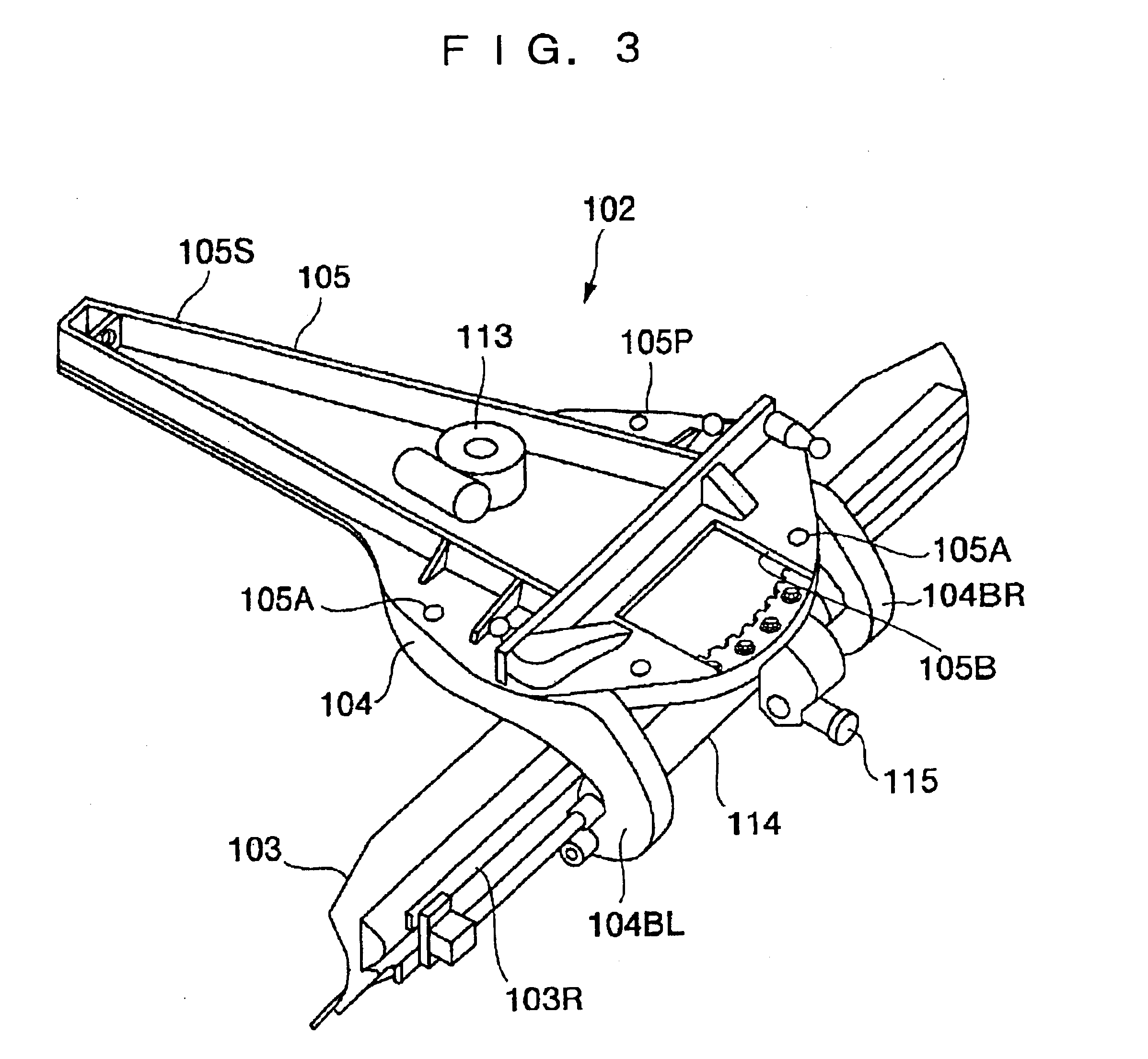
FIG. 1 is an outline view of a motor grader 100 being an example of a working vehicle, and FIG. 2 is a side view thereof. As shown in FIGS. 1 and 2, a drawbar 105 is swingably mounted to a front end portion of a front frame 106 of the motor grader 100, and a blade 103 is supported slidably in a lateral direction by a circle 104 rotatably mounted to the drawbar 105 to constituted a working machine 102. The drawbar 105 is raised and lowered up and down by synchronous extension and contraction of lift cylinders 111a and 111b, is tilted in an up and down direction by different extensions and contractions of the lift cylinders 111a and 111b, and swings to the left and right with respect to a traveling direction of the vehicle body by extension and contraction of a blade shift cylinder 114. The circle 104 is driven by a hydraulic motor 11...


PUM


Abstract

A circle structure of a motor grader excellent in durability at low maintenance cost. For this purpose, the circle structure includes a drawbar (105), at least one guide shoe (213) attached to the drawbar, an integrated ring-shaped circle gear (211) rotatably supported by the guide shoe, a plurality of circle gear mounting bolts (215) placed at equal pitches on a mounting pitch circle of the circle gear, and a circle (104) which is mounted to the circle gear by the circle gear mounting bolts and rotatable with respect to the drawbar.

Description

TECHNICAL FIELDThe present invention relates to a circle structure of a motor grader.BACKGROUND ARTIn a motor grader 10 that is a working machine, a drawbar 16A is swingably mounted to a front end portion of the motor grader 10, and a blade 12A is supported slidably in a lateral direction by a circle 14A rotatably mounted to the drawbar 16A. The circle 14A has a blade support 14B to support the blade 12A. The circle 14A has an integrally formed circle gear (not shown). To rotate the blade 12A, the motor grader 10 moves the circle gear by a pinion gear (not shown) to rotate the blade 12A in a left and right direction with respect to a forward traveling direction of the motor grader 10, thereby performing a desired operation. However, a rotational angle of the blade 12A is an angle in a predetermined range, for example, in a range of 90 degrees in most cases, and therefore the circle gear is worn and broken at a specific spot. When the circle gear is worn and broken, the entire circle...

Claims


Application Information

Patent Timeline
IPC IPC(8): E02F3/76E02F3/80
CPCE02F3/764E02F3/7654E02F3/765E02F3/7645
Inventor MAEDA, KENICHIMISUDA, KENJI
Owner KOMATSU LTD
Why Eureka
Try Eureka