
Fluid emulsification systems and methods

a technology of emulsification system and liquid, applied in the field of liquid emulsification system and method, can solve the problems of no longer optimal previously optimized carburetor and the next largest available carburetor, and achieve the effect of easy integration into existing liquid emulsification system

Inactive Publication Date: 2005-02-08
SATTERFIELD JOHN R
View PDF34 Cites 12 Cited by
  • Summary
  • Abstract
  • Description
  • Claims
  • Application Information

AI Technical Summary

Benefits of technology

It is an object of this invention to provide an improved fuel emulsion device that is easily incorporated into existing carburetor systems.
The above and other objects of the invention are also achieved by forming an insert to be placed over the carburetor and having a number of air runners corresponding to the number of runners or carburetor throats in the host carburetor. Each runner of the insert can have a constant diameter throat, or can alternatively have decreasing or increasing throat dimensions. In one embodiment the throats of the insert can be a venturi therein that either augments, effectively repositions, blends with or replaces a standard venturi in a standard location in the throat of a carburetor. By altering the location of the venturi to the location of the optimum signal (for drawing an optimum mixture of emulsified fuel into the intake flow stream) the highest efficiency of the carburetor can be attained.

Problems solved by technology

This may occur where the one size carburetor is too small, but the next largest available carburetor is too big.
With a restrictor 188 between a carburetor and an intake manifold on an engine, a previously optimized carburetor is no longer optimal.

Method used


Image

  • Fluid emulsification systems and methods
  • Fluid emulsification systems and methods
  • Fluid emulsification systems and methods

Examples


Embodiment Construction

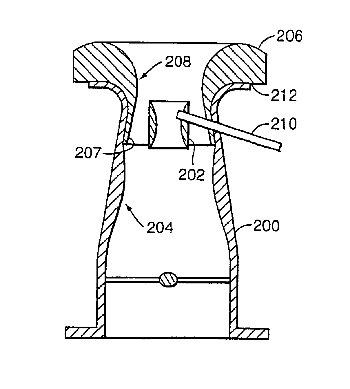
In describing a preferred embodiment of the present invention, references are made to FIGS. 1-19 of the drawings in which like numbers refer to like features of the invention. None of these figures present the invention and the environment in true scale. That is, the relationship and sizes of various illustrated components are presented to convey the essence of the invention and provide a teaching of the invention. In an actual embodiment, the emulsion tube when used in a conventional carburetor for instance would have a diameter on the order of 0.25 inches. Moreover, in alternative embodiments (e.g., jet engines) the scale would be much larger. Once the invention is understood in its preferred form, one of ordinary skill in the art can easily apply it to applications other than a conventional carburetor.

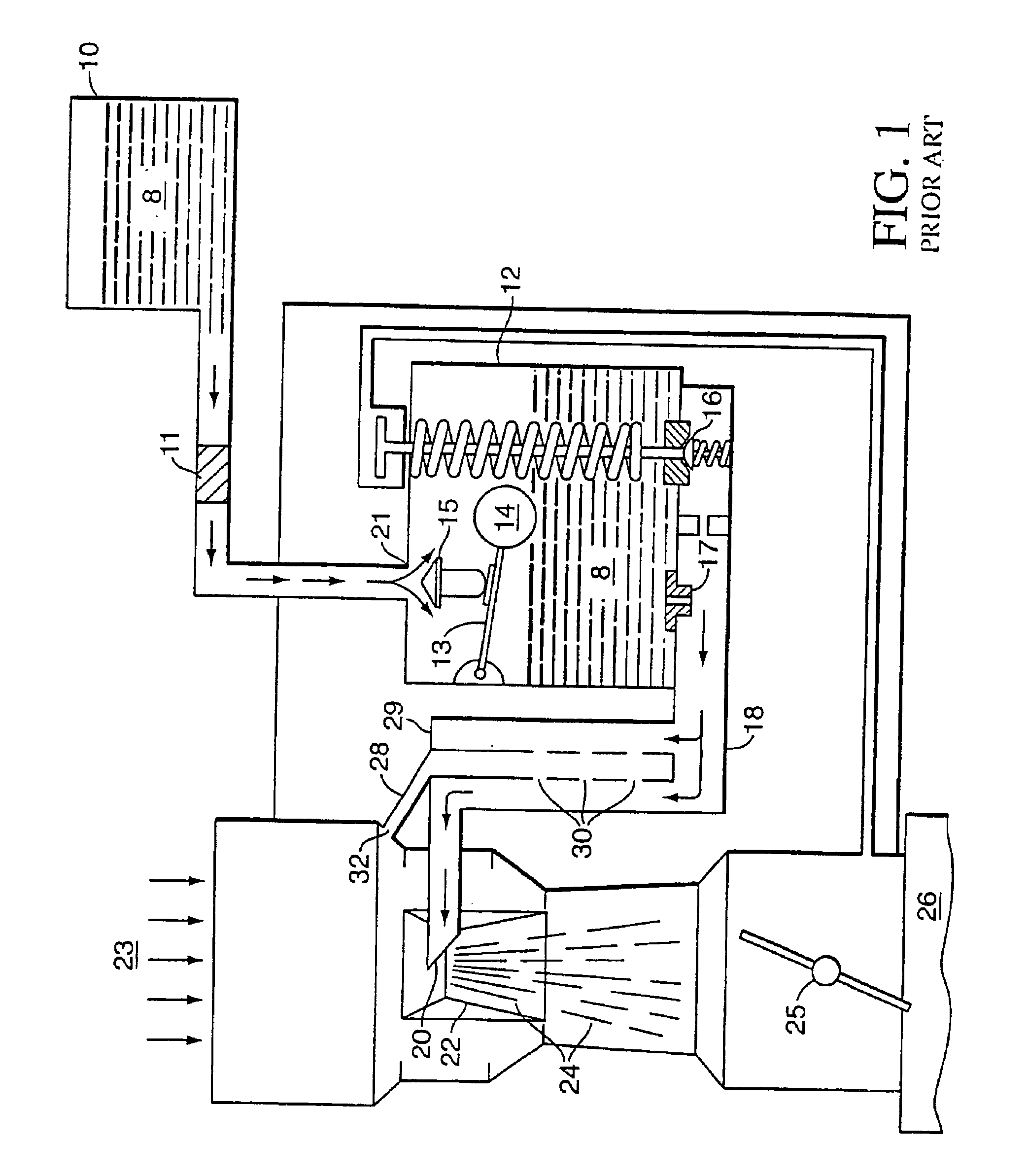
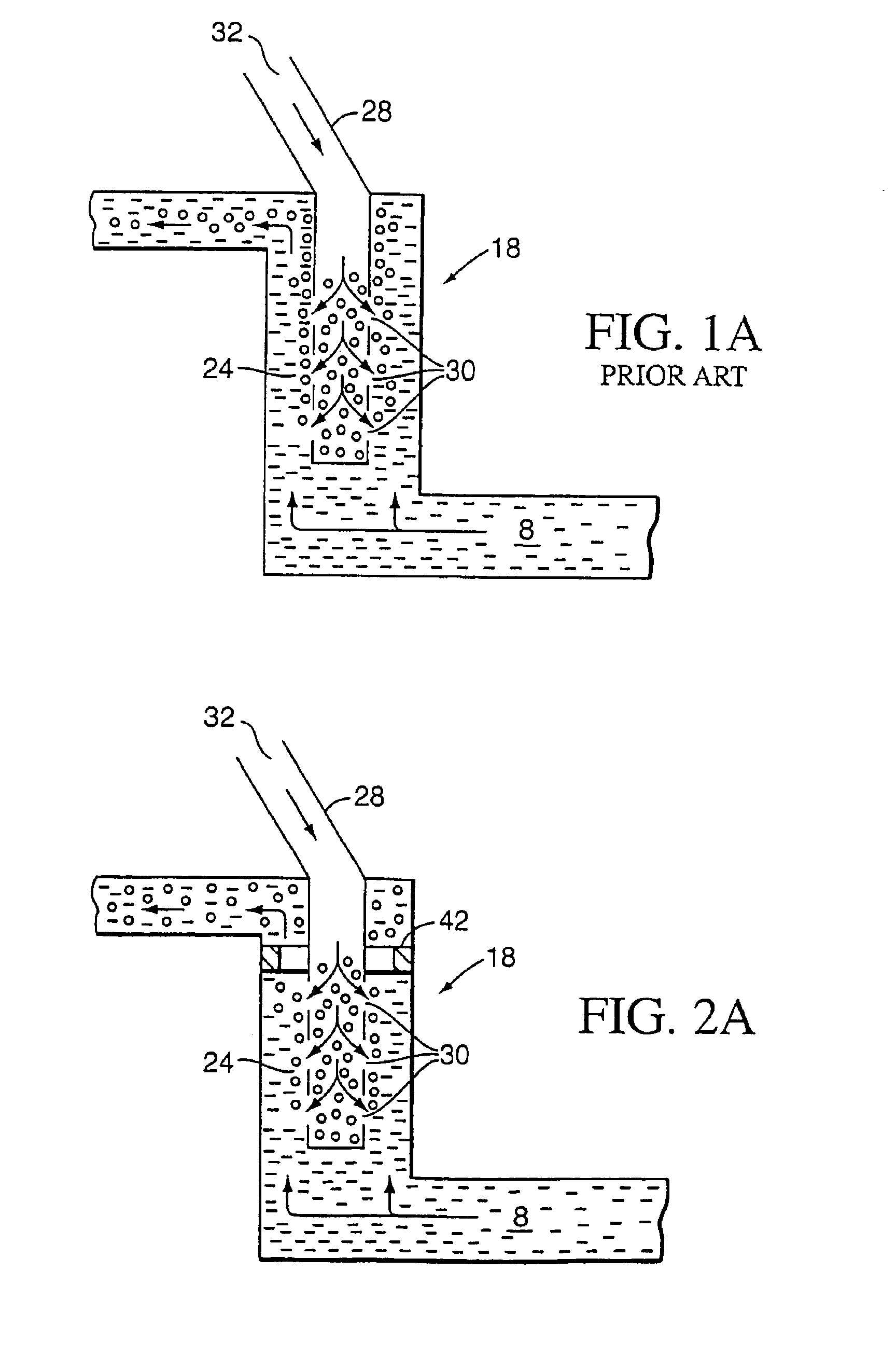
FIGS. 1 and 1A depict a prior art form of carburetor. Fuel 8 flows from a source 10 in the direction of the arrows and passes through a screen or filter 11, a needle and seat valve ...


PUM

PropertyMeasurementUnit
diameteraaaaaaaaaa
diameteraaaaaaaaaa
pressureaaaaaaaaaa

Abstract

This invention describes systems and methods for mixing two fluids. A first fluid, usually fuel, can be passed through a primary passage that typically leads to a carburetor or other inlet to a combustion engine. A second fluid, usually air, can be mixed with the first by introducing it to the primary passage through an inlet located upstream in the primary passage. The mixture of fluids can then be further emulsified by passing it over a plurality of obstructions, such as a threaded interior surface of the primary passage, located within the primary passage downstream of the inlet.

Description

FIELD OF INVENTIONThis invention relates generally to fluid emulsification systems and methods, including fluid delivery systems for combustion engines and similar applications, including gas, diesel and jet engines. More specifically, this invention also relates to systems and methods that promote uniform and homogenous emulsification of a liquid (such as fuel) by blending a gas (such as air) with the liquid and then supplying this blended mixture to an engine. One application of the invention is in fuel delivery systems, such as used for internal combustion (including gas and diesel engines) or jet engines, where thorough and homogeneous emulsification of the fuel and air, and the supply of this mixture in augmentation of a primary fuel supply system, results in greatly increased engine efficiency. Also disclosed are improvements in carburetor fuel passages, including the relative positioning of boosters and venturis in carburetors and other flow enhancing attachments that have an...

Claims


Application Information

Patent Timeline
Patent Type & Authority Patents(United States)
IPC IPC(8): B01F5/06B01F5/04C10L1/00F02M7/10F02M7/00F02M19/00F02M19/03B01F3/04B01F5/00
CPCB01F5/0451B01F5/0463B01F5/0473B01F5/061C10L1/00F02M7/103F02M19/03B01F3/04099B01F2005/0034Y10S261/56Y10S261/26Y10S261/12B01F2215/0086F02M7/23B01F23/23B01F2025/918B01F25/31331B01F25/3131B01F25/3141B01F2101/503B01F25/4314B01F25/431971
Inventor SATTERFIELD, JOHN R.
Owner SATTERFIELD JOHN R
Learn More