Cylinder head gasket

a gasket and cylinder head technology, applied in the direction of engine sealing, machine/engine, engine sealing arrangement, etc., can solve the problems of deterioration of sealing ability due to heat load, insufficient treatment, and difficulty in applying gaskets to recent engines, so as to reduce the quantity of bead rigidity, prevent damage caused by bending process, increase the effect of bead width

Inactive Publication Date: 2005-02-08
ISHIKAWA GASKET CO LTD
View PDF10 Cites 20 Cited by
  • Summary
  • Abstract
  • Description
  • Claims
  • Application Information

AI Technical Summary

Benefits of technology

[0041]According to the structure as described above, the foot portions of the inner peripheral side bead and the outer peripheral side bead are prevented from overlapping each other, and it is facilitated to presume a relationship between the increase of the bead width and the reducing quantity of the bead rigidity.
[0042]Further, in the respective cylinder he

Problems solved by technology

Thus, there has been a problem such that, in view of the tendency of making the engine small to allow the space between the cylinder bores to become narrow, it is hard to apply the gasket to the recent engine.
Also, there has been a problem such that, in order to distribute the tightening force uniformly by tightening the bolts, deterioration of sealing ability due to heat load and heat stress, which have recently been a problem, is not sufficiently dealt with.
As the pressure in a cylinder (Pmax) of a diesel engine becomes high, the problem of the deterioration of the sealing ability by the heat load and heat stress has become the public attention.
The problem arises at, for ex

Method used


Image

  • Cylinder head gasket
  • Cylinder head gasket
  • Cylinder head gasket

Examples


first embodiment

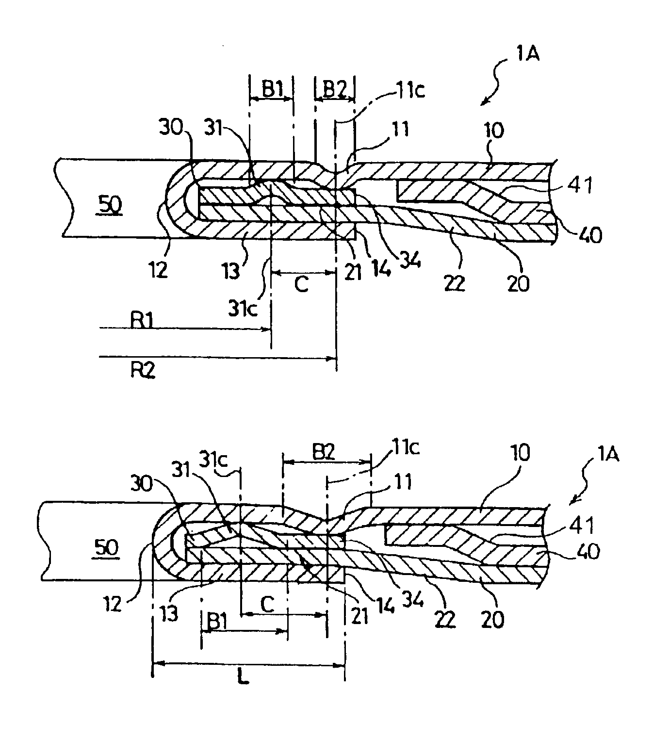
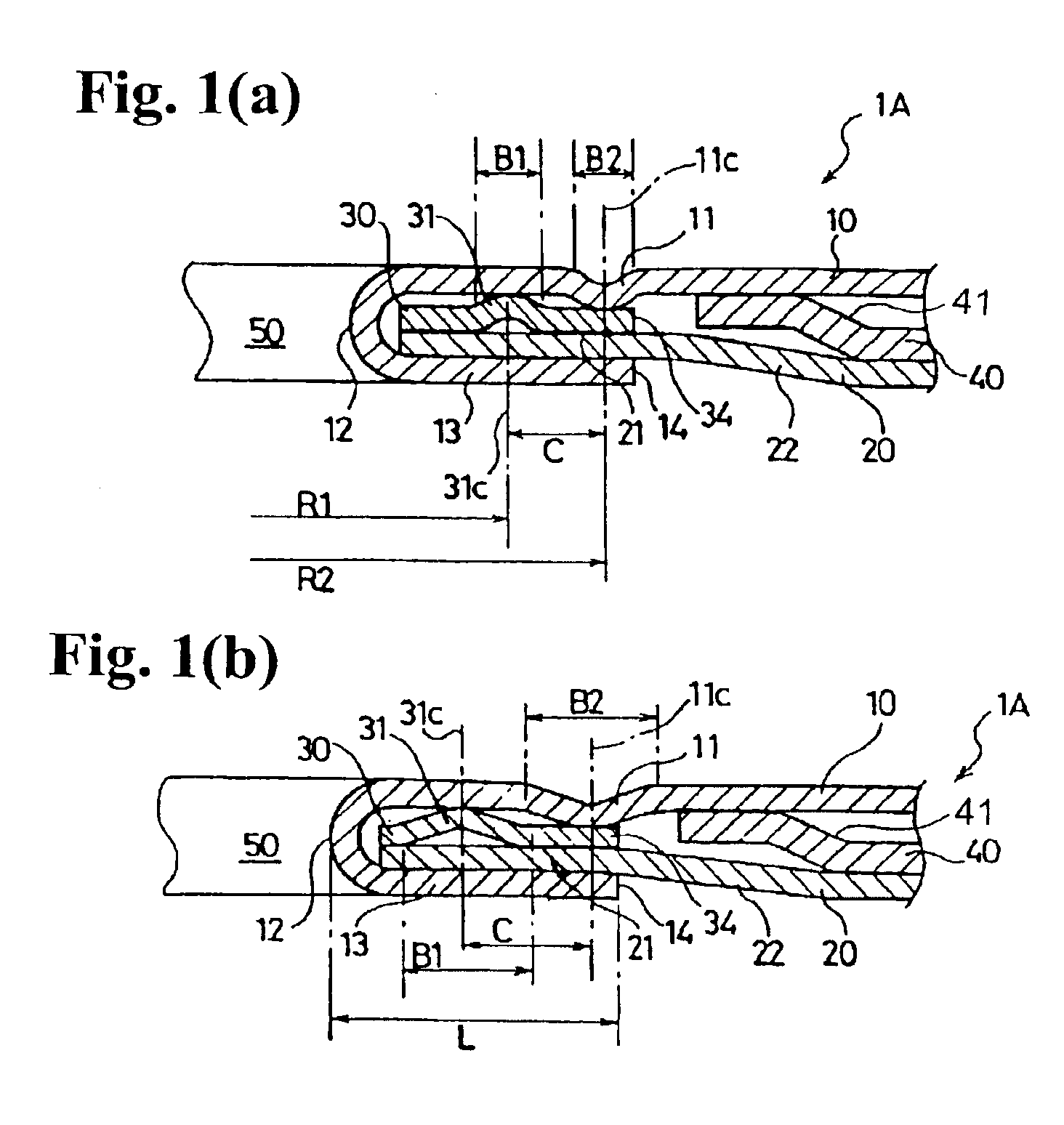
[0062]In the first embodiment of the invention, as shown in FIGS. 1(a) and 1(b), a bead width B1 of the inner peripheral side bead 31 and a bead width B2 of the outer peripheral side bead 11 are formed to be partially and gradually wider at a position where the heat load is locally high along the periphery of the cylinder bore 50. FIG. 1(a) shows a structure of the portion where the heat load does not become high, while FIG. 1(b) shows a structure of the portion where the heat load becomes high.

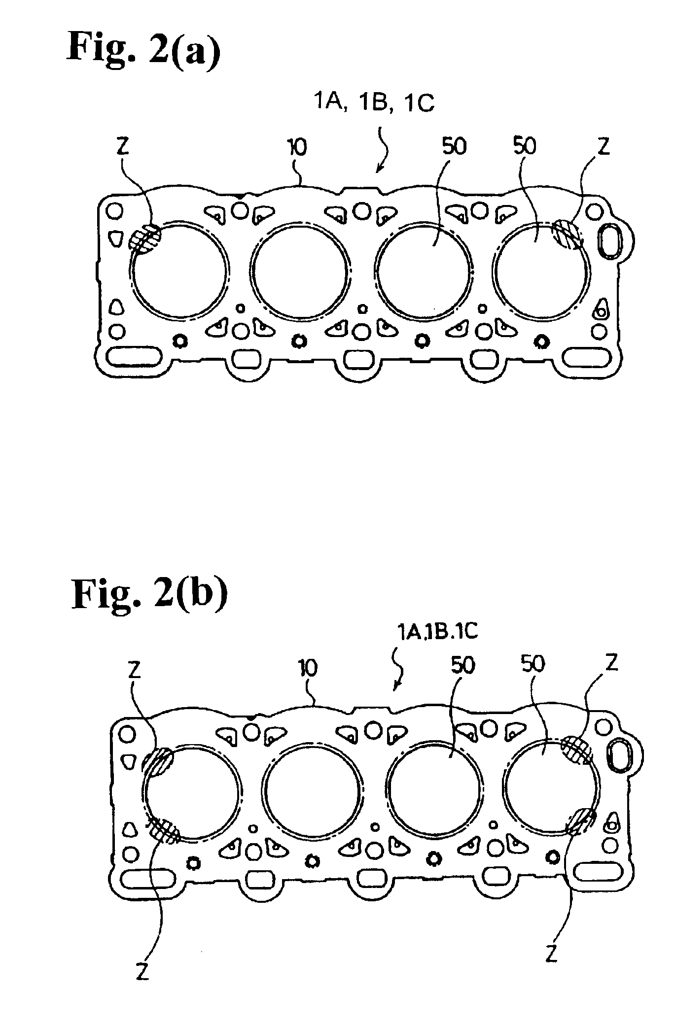
[0063]While the portion where the heat load becomes locally high is different depending on a type of an engine, FIG. 2(a) shows portions where the heat load is locally high. In a four cylinder engine as shown in FIG. 2(a), the heat load becomes locally high at two oblique line portions Z of the cylinder bores 50 on both exhaust sides. Also, as shown in FIG. 2(b), the heat load becomes high locally at two oblique line portions Z of the cylinder bores 50 on both exhaust sides and at two oblique...

second embodiment

[0071]Next, a cylinder head gasket 1C of a second embodiment of the invention will be explained.

[0072]In the gasket 1C of the second embodiment, instead of changing the bead widths B1, B2 of the inner peripheral side bead 31 and the outer peripheral side bead 11 with respect to the portion Z where the heat load increases locally, as shown in FIGS. 4(a) and 4(b), a distance C between the inner peripheral side bead 31 and the outer peripheral side bead 11 is partially and gradually enlarged. The gasket of the second embodiment is the same as that of the first embodiment except for the structure as described above.

[0073]In the second embodiment, the clearance or space C between the inner peripheral side bead 31 and the outer peripheral side bead 11 is partially enlarged with respect to the portion Z where the heat load is locally high, so that the space between the bead 31 and the bead 11, facing each other inside the folded-back portion of the first surface plate 10, is widened, and t...

third embodiment

[0075]A cylinder head gasket of the third embodiment is applied to the one having cylinder bores 50A, 50B where the heat loads at the plural peripheral portions are different, as shown in FIG. 6.

[0076]As shown in FIGS. 5(a), 5(b) and 6, in a cylinder head gasket 1D of the third embodiment, the surface pressure generated by the heat load is different depending on the positions of the cylinder bores 50A, 50B. More specifically, as shown in FIG. 6, in the cylinder bores 50A, 50B, 50B, 50A disposed in series, the heat load generated on the peripheral portions of the cylinder bores 50B located on the central side is higher than that of the cylinder bores 50A located on both sides.

[0077]In view of the above situation, the bead width BB1 of the inner peripheral side bead 31B and the bead width BB2 of the outer peripheral side bead 11B are made wider, at the peripheral portions of the cylinder bore 50B where the surface pressure due to the heat load becomes high, than the bead width BA1 of ...


PUM


Abstract

A cylinder head gasket for an internal combustion engine includes a first metal plate having first holes and first beads formed around the respective first holes, and a second metal plate disposed under the first metal plate and having a second bead extending toward the first metal plate. A distance between the first and second beads or a width of at least one of the first and second beads at a high heat load portion of the cylinder bore is formed to be greater than a distance between the first and second beads or a width of at least one of the first and second beads at a low heat load portion of the cylinder bore to thereby reduce a surface pressure at the high heat load portion.

Description

BACKGROUND OF THE INVENTION AND RELATED ART STATEMENT[0002]The invention relates to a cylinder head gasket having two surface plates and a bead plate, more particularly, a cylinder head gasket capable of generating an optimum surface pressure with respect to portions where heat load is high in a peripheral portion of a cylinder bore.[0003]As a gasket for sealing joint surfaces between a cylinder head and a cylinder block of an internal combustion engine, there has been used a cylinder head gasket formed by laminating thin metal plates on which a sealing device is formed along a periphery of a hole to be sealed.[0004]In view of demands for making an internal combustion engine small and light weight, especially a small type diesel engine, engine members, such as a cylinder head and a cylinder block, have been made of an aluminum alloy or the like with a relatively low rigidity. Since the engine has been designed to have a high output, as the pressure (Pmax) in a cylinder is increased,...

Claims


Application Information

Patent Timeline
IPC IPC(8): F16J15/08F02F11/00
CPCF16J15/0825F16J2015/0862F16J2015/0837F02F11/00F16J15/08
Inventor MIYAOH, YOSHIOYASUDA, KISHO
Owner ISHIKAWA GASKET CO LTD
Why Eureka
Try Eureka