Vehicle suspension

a technology for vehicle suspensions and suspensions, applied in the direction of loading/unloading vehicle arrangment, transportation items, transportation and packaging, etc., can solve the problems of inherently torque reactive, general proportional driveline vibration in vehicles, particularly heavy-duty trucks, and achieve excellent roll stability characteristics and facilitate adjustment of axle pinion angles

Inactive Publication Date: 2005-02-08
HENDRICKSON USA L L C
View PDF13 Cites 43 Cited by
  • Summary
  • Abstract
  • Description
  • Claims
  • Application Information

AI Technical Summary

Benefits of technology

In a preferred aspect, the frame hangers include control rod mounting features. These features permit the incorporation of longitudinally extending control rods outboard of the vehicle frame rails. The frame hangers also preferably include features that facilitate installation and assembly of the suspension components, specifically the beams.
In still another preferred aspect, the bottom pad for the axle clamp assembly includes a single leg having a curved surface to accommodate the curved portion of a D-shaped bar pin bushing that connects the axle clamp assembly to the beam through its axle pivot bore. This construction facilitates adjustment of axle pinion angle, as desired. The bottom pad also preferably includes shock damper mounting features.
In yet another preferred aspect, the connection assembly that joins the crossbrace at corresponding beam ends includes a machine taper joint and a square-like geometry, exhibiting excellent roll stability characteristic during vehicle operation.

Problems solved by technology

Such increases have magnified the problems of driveline vibration associated with trailing arm air suspensions, which are inherently torque reactive.
It has been found that driveline vibration in vehicles, particularly heavy-duty trucks, is generally proportional to the severity of frame rise and wheel hop, and vice versa.
Most air suspensions that are adequately roll stable do not provide adequate mobility.
Conversely, most air suspensions that provide mobility do not provide sufficient roll stability.
Further, such suspensions have reduced the comfort and ride characteristics of the suspension.
These prior art non-torque reactive suspensions are also generally heavy, translating into reduced payload capacity in commercial vehicle applications.
Such suspensions are also generally expensive to manufacture in terms of increased component parts and they require lengthy installation and assembly time, which further increases their manufacturing expense.
The prior art non-torque reactive suspensions also have generally low roll stability, thereby limiting use of the vehicle to certain, limited applications.

Method used


Image

  • Vehicle suspension
  • Vehicle suspension
  • Vehicle suspension

Examples


Embodiment Construction

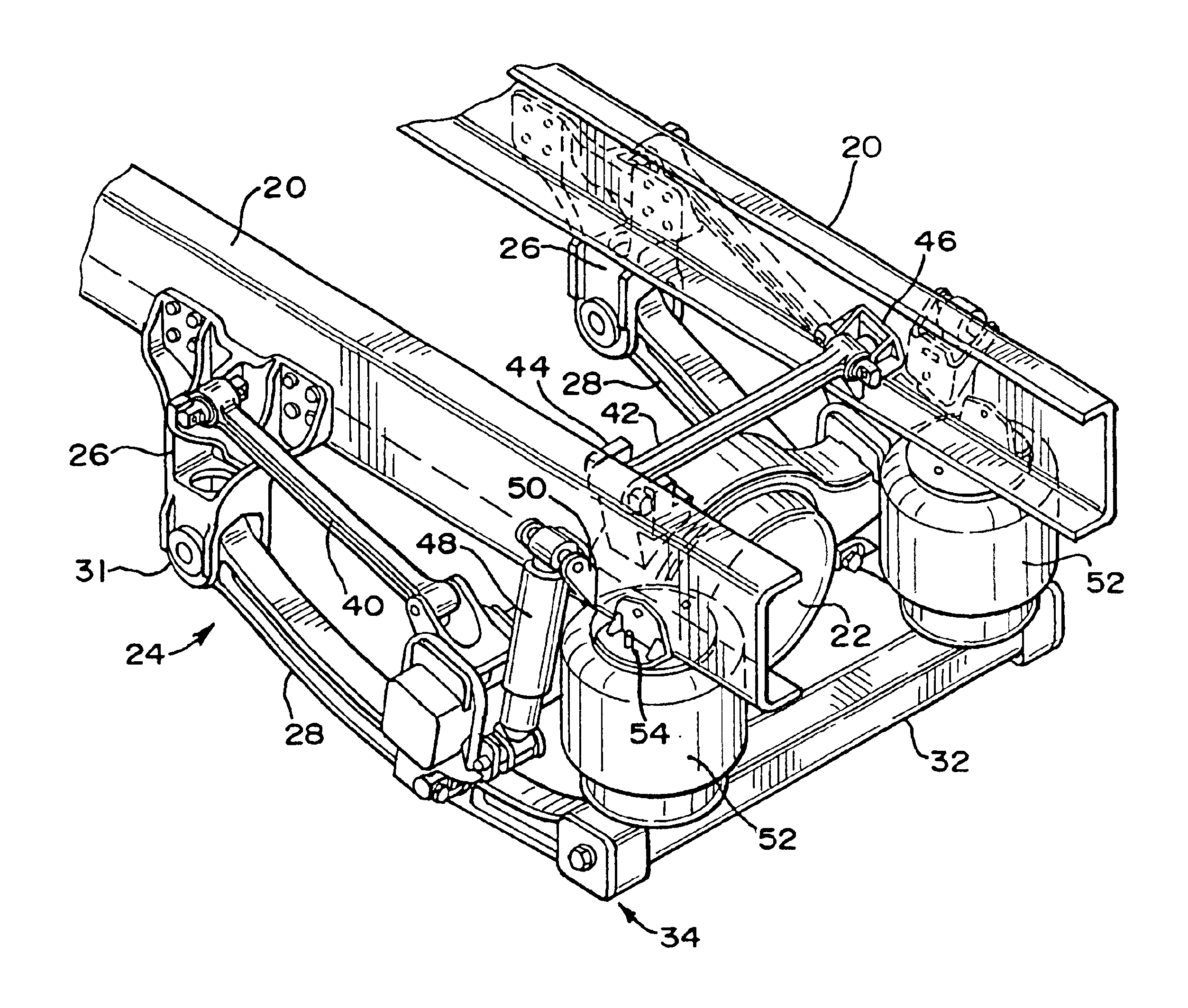
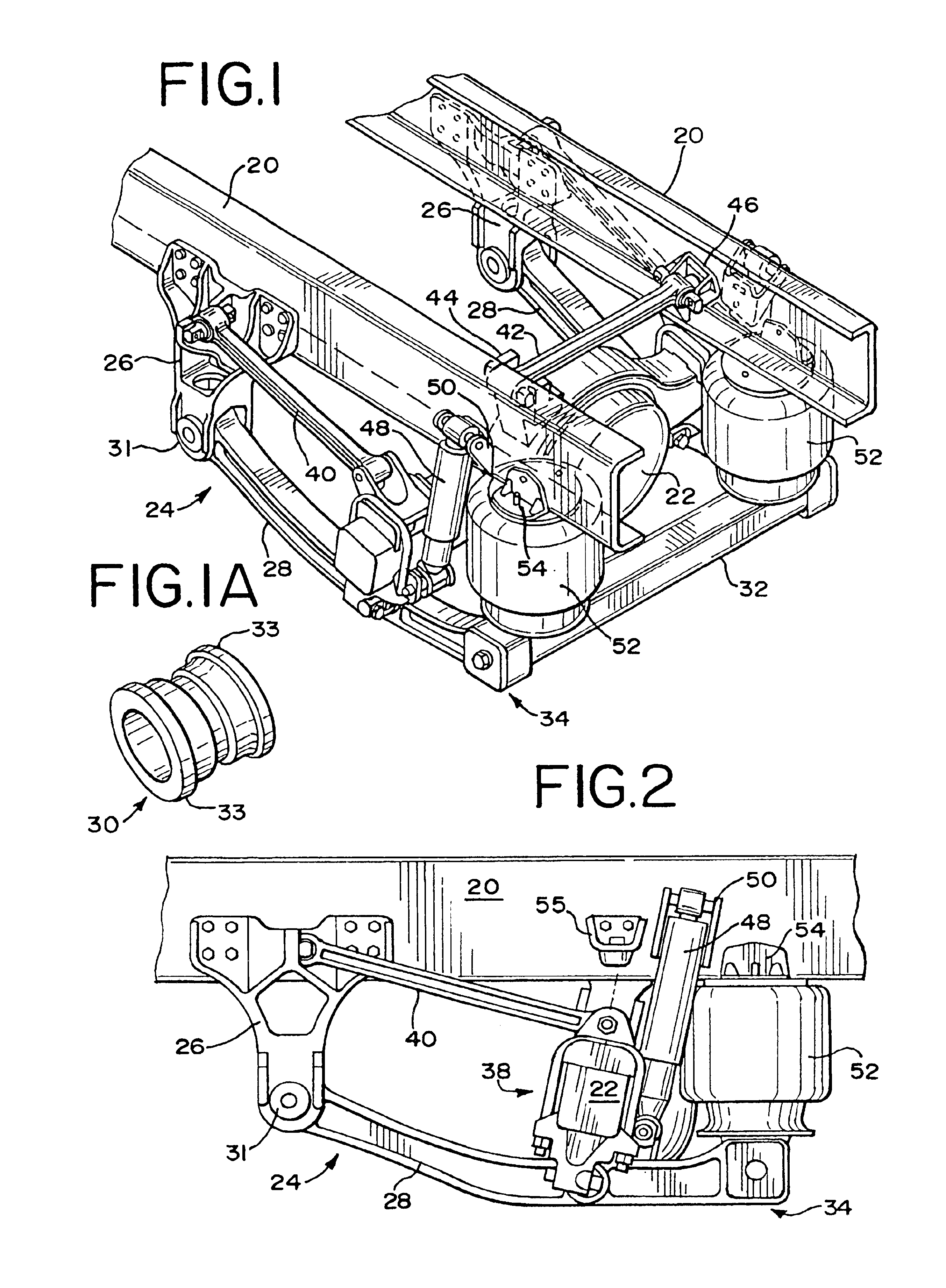
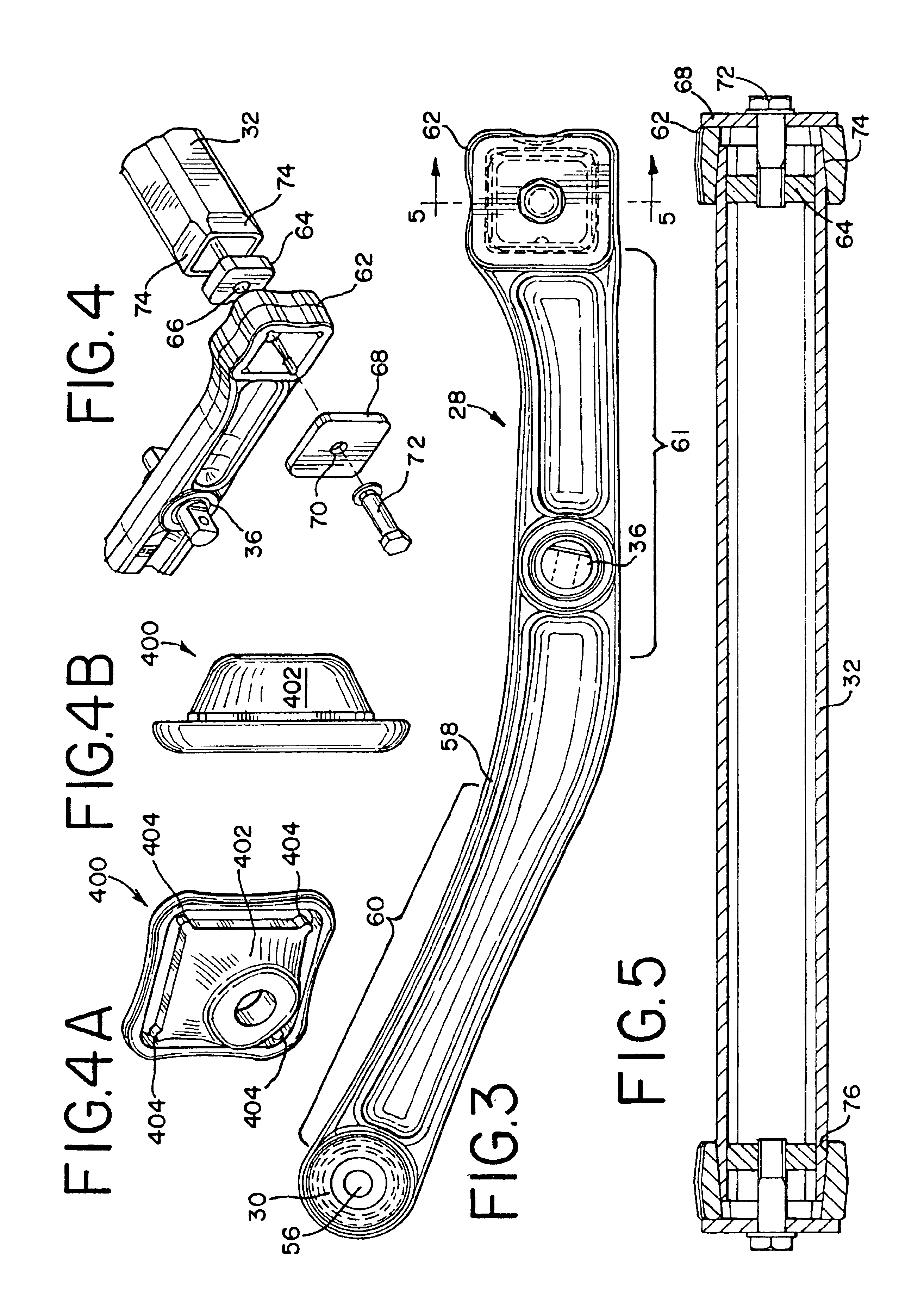
FIGS. 1 and 2 illustrate components used in association with a vehicle, such as a heavy-duty truck and the like (not shown). The vehicle includes longitudinally extending frame rails 20 positioned on opposite sides of the vehicle and having a preferred C-shaped configuration. The vehicle further includes a drive axle having a housing illustrated in FIG. 1 by reference numeral 22. The drive axle for the vehicle extends laterally across the vehicle and is used to mount tires (not shown) driven by a vehicle engine (not shown).

In addition to the foregoing, the vehicle further includes a suspension generally designated by reference numeral 24, which connects the drive axle housing 22 to frame rails 20—20 positioned on opposite sides of the vehicle.

As will be appreciated, with respect to suspension 24, the majority of the components positioned on one side of the vehicle will have correspondingly similar components positioned on the other side. Accordingly, in this description, when refere...


PUM


Abstract

A non-torque reactive air suspension exhibiting excellent roll stability characteristics is shown to include frame hangers mounted to frame rails extending longitudinally on opposite sides of a vehicle. Longitudinally extending beams are connected to the frame hangers at one end and extend parallel to the frame rails. At their other ends, the beams are joined by a crossbrace extending laterally across the vehicle centerline. In a central portion thereof, the beams have an axle pivot bore to which an axle clamp assembly is connected, the axle clamp assembly clamping a drive axle housing for the vehicle. The axle pivot bore is generally aligned with the drive axle. A control rod assembly is connected to suspension or frame components. Together with the beams, the control rod assembly forms a parallelogram configuration wherein the beams form the lower linkages of that configuration and the control rods included within the control rod assembly form the upper linkages of that configuration.

Description

BACKGROUND OF THE INVENTIONThe present invention relates generally to innovations and improvements in vehicle suspensions. More particularly, the present invention relates to a new and improved vehicle suspension that does not react significantly to torsional forces produced by high-torque drivetrain such as those utilized in heavy-duty trucks and the like, yet exhibits excellent ride and handling characteristics.For several reasons, including use of higher horsepower engines and advances in engine technology, there have been increases in the torque output of heavy-duty truck engines. Such increases have magnified the problems of driveline vibration associated with trailing arm air suspensions, which are inherently torque reactive. When increased torque is applied to the axle of a truck equipped with such a torque reactive suspension, such as during acceleration, the frame of the truck rises up and away from the drive axle. This condition is known and referred to in the art as “fram...

Claims


Application Information

Patent Timeline
Patent Type & Authority Patents(United States)
IPC IPC(8): B60G7/04B60G9/00B60G7/00
CPCB60G9/00B60G2206/601B60G2200/315B60G2200/341B60G2202/136B60G2202/152B60G2204/126B60G2204/128B60G2204/143B60G2204/1482B60G2204/416B60G2204/4302B60G2204/4306B60G2204/4502B60G2206/124B60G2206/60B60G2200/314
Inventor DUDDING, ASHLEY THOMASFORREST, CHRISTOPHER WAYNESTUART, JOHN WAYNETHOMAS, JASON STEBYMARQUEZ, PEDRO RAMSES BANDADANKOW, MARK WILLIAM
Owner HENDRICKSON USA L L C
Why Eureka
Try Eureka