Bearing unit, production method therefor and spindle motor

a technology of bearing unit and spindle motor, which is applied in the direction of bearing unit rigid support, sliding contact bearing, mechanical apparatus, etc., can solve the problems of reduced thickness of motor, increased number of parts, and complicated structure, and achieves the shape and size of the grooves that are precisely obtained, not easily loosened, and easy to work.

Inactive Publication Date: 2005-02-08
HITACHI POWDERED METALS COMPANY +1
View PDF6 Cites 19 Cited by
  • Summary
  • Abstract
  • Description
  • Claims
  • Application Information

AI Technical Summary

Benefits of technology

Therefore, an object of the present invention is to provide a spindle motor, a bearing unit, and production method therefor capable of improving the fitting performance between a rotating shaft and a bearing, and restraining the loose of the magnetic powder particles, thereby achieving reduction of wear and precise rotation.
According to the bearing unit of the invention, a rotating shaft is inserted into the bearing and the magnetic fluid as a lubricating fluid is provided between the bearing and the rotating shaft. The magnetic fluid is magnetized due to dispersion of magnetic particles, and the magnetic force holds the magnetic fluid in the lubricating pathway, that is, the clearance between the bearing and the rotating shaft, whereby lubrication is effectively performed, and leakage of the lubricating fluid is restrained. Magnets are not required since the bearing functions as a magnet for holding the magnetic powder, and the structure thereof can therefore be simple without any additional parts, and the thickness of the structure can be reduced.
The bearing unit of the invention is essentially characterized in the pores existing on the bearing surface of the bearing being sealed by a resin. For this feature, the bearing surface of the bearing is lubricated by the resin, and the fitting performance between the bearing and the rotating shaft is improved in spite of dispersion of the magnetic powder. The resin adheres the powders consisting of the bearing to the bearing surface and restrains loose of the powders. As a result, wear due to the powders existing between the bearing and the rotating shaft is restrained, and vibration performance is therefore stable, and high precise rotation is obtained.
According to the preferred feature of the invention, the bearing surface of the bearing has grooves for generating dynamic pressure. In this feature, the dynamic pressure generated by the magnetic fluid in the grooves does not leak since the pores are sealed, and high rigidity of the bearing is maintained.
In the production method of the invention, the bearing may have a clearance of approximately a few μm to 10 μm with respect to the housing, and an adhesive is charged into the clearance. The clearance may regulate the amount of the adhesive, and sufficient securing strength between the bearing and the housing.
In the production method of the invention, grooves for generating dynamic pressure may be formed on a bearing surface of the bearing. The grooves may be formed, for example, in a sizing process in which the bearing hole is finished to the designed size. In this production method, the bearing surface is not easily broken and the powders consisting thereof are not easily loosened therefrom since the pores are filled with the resin. As a result, the grooves are easily worked, and shape and size of the grooves are precisely obtained.

Problems solved by technology

Such a bearing unit is suitable for HDDs in which oil leakage is not desirable.
However, the structure in which a magnet is located in a bearing results in an increase of number of parts and a complicated structure, and this is not desirable for the reduction of thickness of motors.
In the sintered bearing containing a magnetic powder, relatively hard magnetic powder exists on a bearing surface, and the rotating shaft is not easy to fit thereto and tends to wear easily.
Furthermore, the magnetic powder existing on the bearing surface is loosened by wear, and the loosened particles function as an abrasive between the rotating shaft and the bearing.
As a result, wear is promoted and vibration characteristics are not stable, precise rotation is not obtained.

Method used


Image

  • Bearing unit, production method therefor and spindle motor
  • Bearing unit, production method therefor and spindle motor
  • Bearing unit, production method therefor and spindle motor

Examples


Embodiment Construction

Embodiments in which the invention is applied to HDD motors will be explained with reference to the drawings hereinafter.

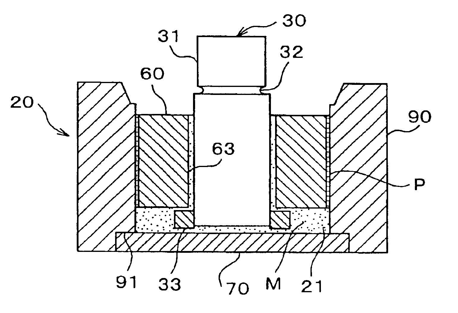
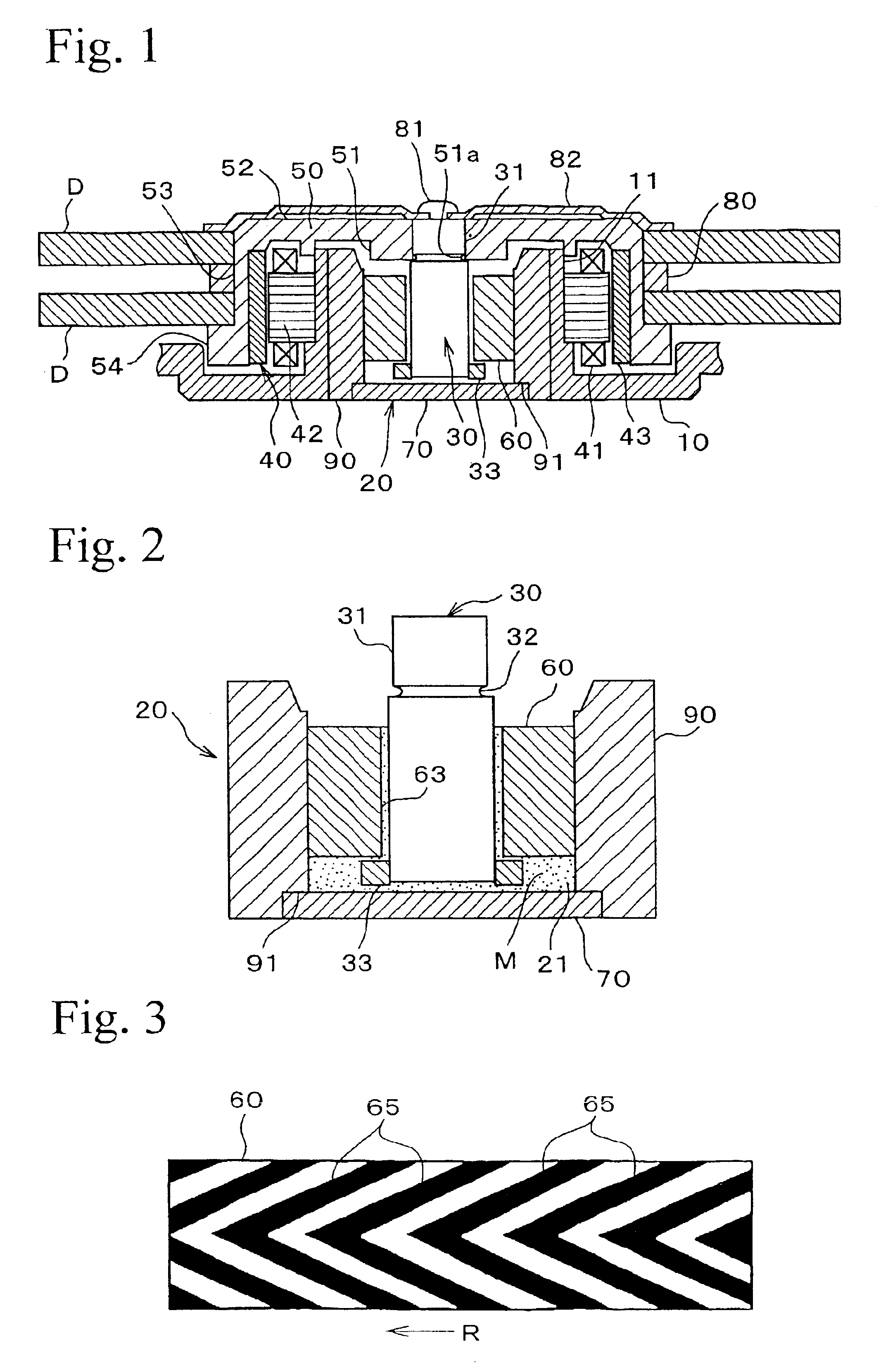
FIG. 1 shows a cross section of a spindle motor. The spindle motor is adapted to rotate two magnetic disks D, and comprises a case 10, a bearing unit 20, a rotating shaft 30 rotatably supported by the bearing unit 20, a motor 40, and a hub 50 which supports the magnetic disk D and is rotated by the action of the motor.

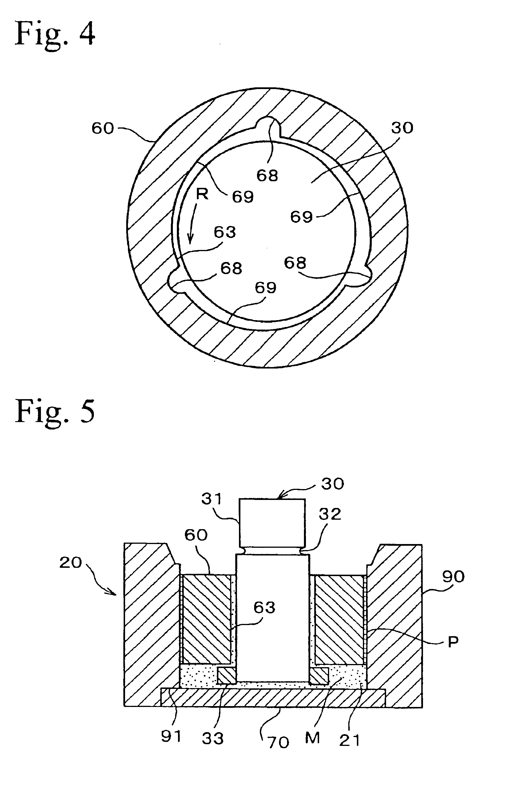
A cylindrical holder 11 protruding upwardly in FIG. 1 is formed at the center of the case 10, and the bearing unit 20 is accommodated therein. As shown in FIG. 2, the bearing unit 20 consists of a cylindrical housing 90, a disk-shaped thrust plate 70 which closes the lower aperture of the housing 90, and a cylindrical bearing 60 accommodated in the housing 90. The thrust plate 70 is fitted into a peripheral recess 91 formed at the inner edge of the lower side of the housing 90, and is secured thereto by means such as caulking, welding, adhering, or t...


PUM

PropertyMeasurementUnit
weight %aaaaaaaaaa
dynamic pressureaaaaaaaaaa
magneticaaaaaaaaaa

Abstract

A bearing unit comprises a bearing 60 formed of a sintered metal in which a magnetized magnetic powder is dispersed in its matrix and at least pores exposed on a bearing surface thereof are sealed by impregnation with a resin; a non-magnetic housing 90 accommodating the bearing 60; and a lubricating fluid M made of a magnetic fluid.

Description

BACKGROUND OF THE INVENTION1. Field of the InventionThe present invention relates to spindle motors mounted in, for example, information devices or acoustic devices which require precise rotation, relates to bearing units installed in such spindle motors, and relates to production methods therefor, and in particular relates to techniques to be used in HDDs (hard disk drives) in magnetic disk units.2. Related ArtAs precise rotation motors used in, for example, HDDs, there have been provided constructions in which a disk is rotated with high precision by a brushless dynamotor. Bearings suitable for these motors comprise a combination of a radial bearing and a thrust bearing respectively supporting the radial load and thrust load of the rotating shaft. These bearings are generally fluid dynamic bearings in which the rotating shaft is supported with high precision due to the dynamic pressure action of a lubricating oil.Lubricating oils have generally been generally used as lubricating f...

Claims


Application Information

Patent Timeline
Patent Type & Authority Patents(United States)
IPC IPC(8): F16C33/04F16C33/10F16C17/10F16C33/14F16C33/20F16C35/02H02K7/08H02K15/14
CPCF16C17/026F16C33/107F16C33/1035Y10T29/49639
Inventor TAKEHANA, TOSHIKAZUTOKUSHIMA, HIDEKAZUSHIKATA, HIDEONII, KATSUTOSHIHIROSE, JUN
Owner HITACHI POWDERED METALS COMPANY
Why Eureka
Try Eureka