Method, apparatus and system for the condensation of vapors and gases

a technology of gas condensation and apparatus, applied in the direction of mixing methods, mixing methods, using liquid separation agents, etc., can solve the problems of not solving the problem of shipping and storage of volatile liquids on a larger scale, and achieve the effect of reducing pressure, reducing velocity, and reducing pressur

Inactive Publication Date: 2005-02-08
VENTURIE
View PDF24 Cites 11 Cited by
  • Summary
  • Abstract
  • Description
  • Claims
  • Application Information

AI Technical Summary

Problems solved by technology

None of these publications seeks to solve problems relating to shipping and storage of volatile liquids on a larger scale.

Method used


Image

  • Method, apparatus and system for the condensation of vapors and gases
  • Method, apparatus and system for the condensation of vapors and gases
  • Method, apparatus and system for the condensation of vapors and gases

Examples


Embodiment Construction

Below is a description of an embodiment of the invention with reference to the drawings.

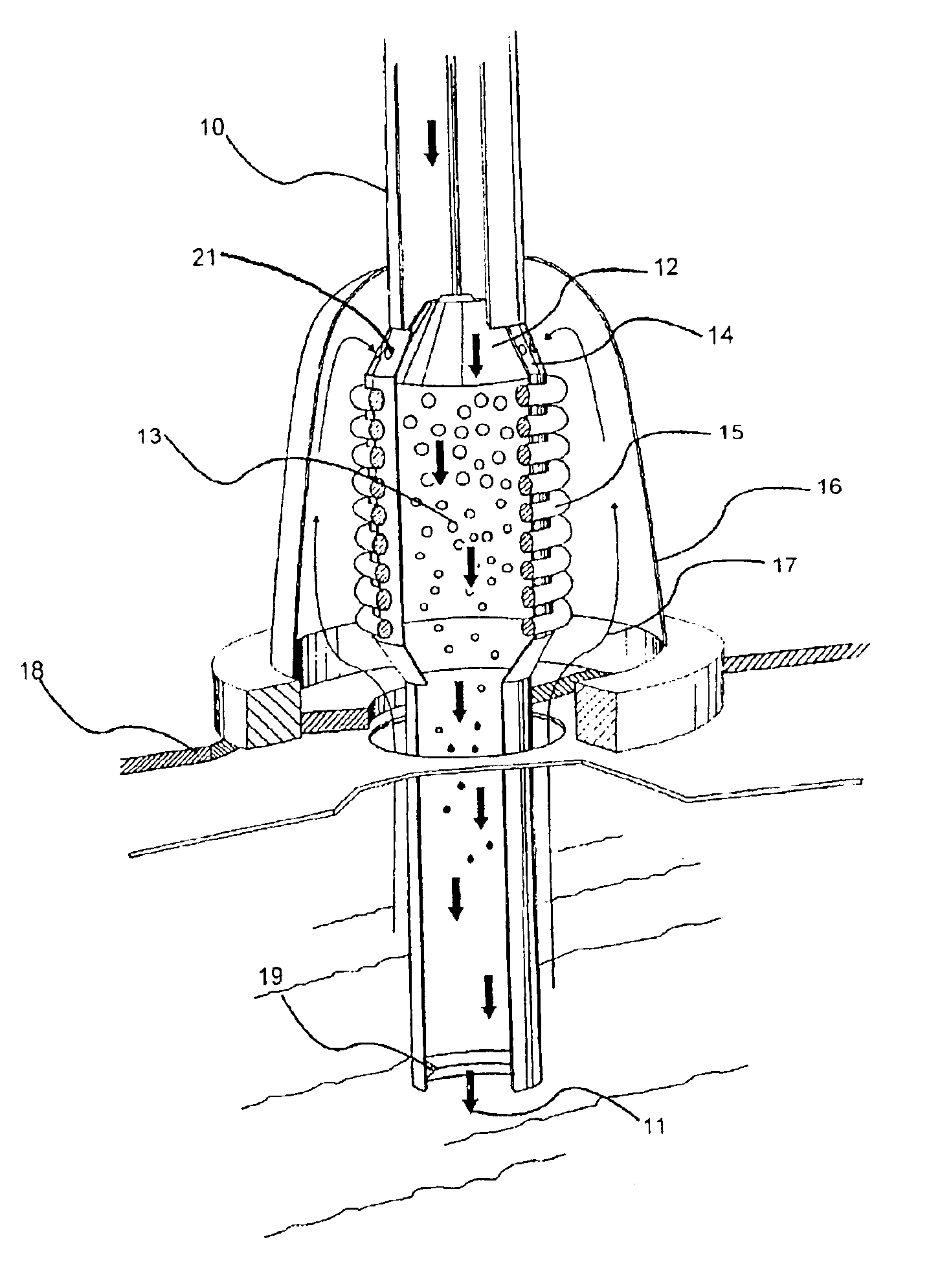
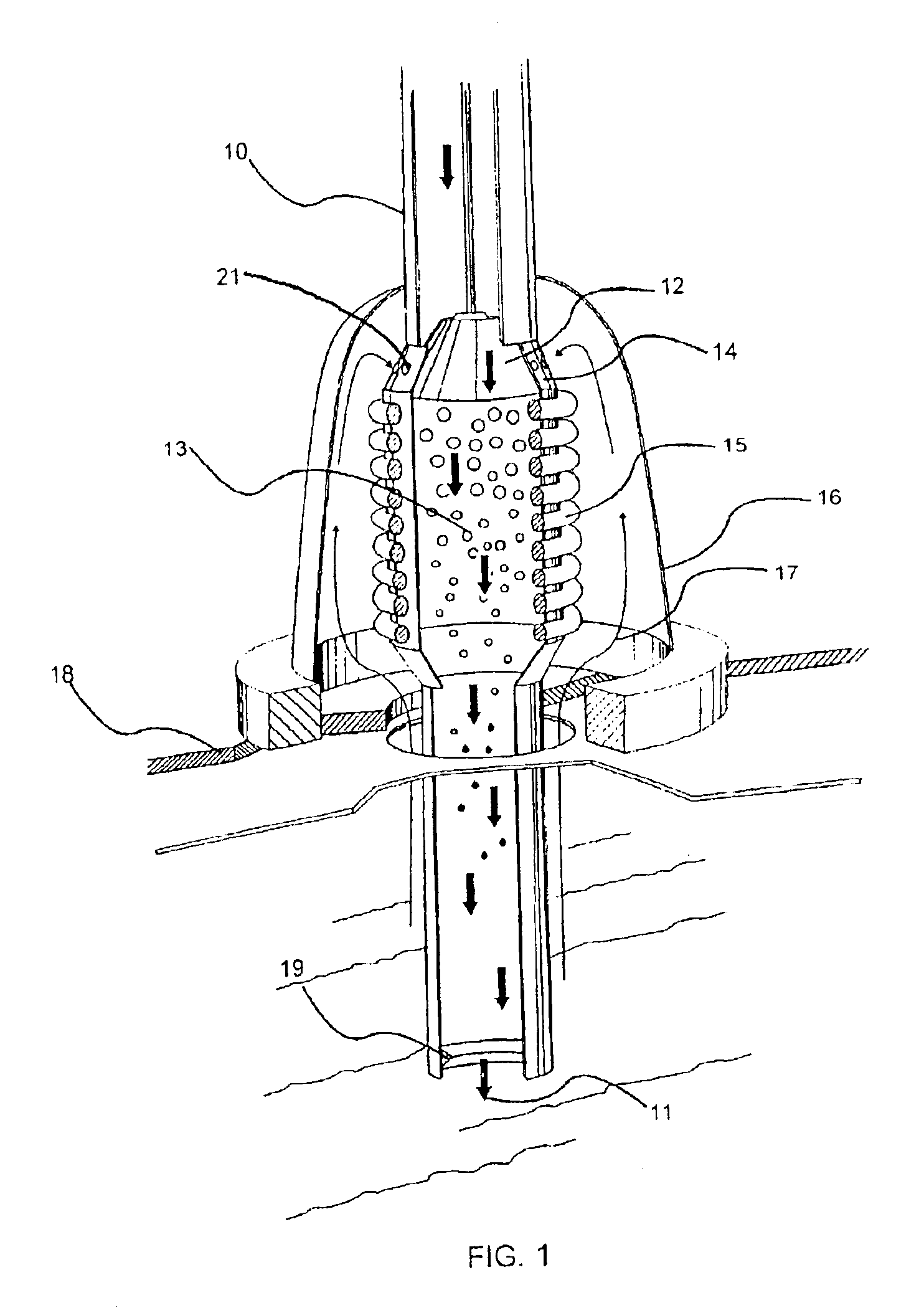
FIGS. 1 and 2 show a condensation apparatus according to the invention. The apparatus is connected to a tube or pipeline 10 for the filling of liquid. A conical piston 12 is attached to the end of the tube or pipeline. The purpose of this is to make a narrow cross section with high liquid velocity in the intersection between the tube 10 and the conical intersection 14 in the tube. The increase in velocity of the liquid flow creates a reduction of pressure. With the correct calibration, this pressure reduction is sufficient to draw the surrounding gas through small port 21 in the conical intersection 14. The support of the conical piston 12 is made such that the cross sectional area can be adjusted depending on the liquid flow rate, to achieve the desired under pressure compared to the ambient conditions. In a chamber 13, after the conical expansion, of the tube 10, with a venturi suction of gas / v...


PUM

PropertyMeasurementUnit
pressureaaaaaaaaaa
velocityaaaaaaaaaa
diameteraaaaaaaaaa

Abstract

A method for condensing fumes or gases from a tank containing a liquid. The method includes leading the liquid into a venturi to create a low pressure at the venturi. Ports are provided in the venturi at the area where the low pressure is created, and gas / vapor is lead to the ports in the venturi in the low pressure area in such a way that the liquid entrains the gas / vapor and forms a fluid, such that the velocity is reduced and the pressure increased to condense the gas / vapor. The fluid is then led from the chamber to a lower part of the tank for further condensation due to the hydrostatic pressure. An apparatus, a system and uses thereof are also described.

Description

BACKGROUND OF THE INVENTION1. Field of the InventionThe present invention is directed to a method, an apparatus and a system for the condensation of gases / fumes / vapors and particularly an apparatus for condensation of fumes during filling and storage of liquid fluids.During storage and filling of fluids in tanks or vessels there is a problem that fumes or gases escapes from the handled or stored liquid. This is particularly prominent with volatile liquids and cooled, liquid gases. These gases or fumes have traditionally been allowed to escape into the atmosphere. This has lead to loss of fluid, pollution, and poor working conditions for people in the area. Examples of such liquids are crude oil, liquid natural gas (LNG) and other hydrocarbons.Volatile liquids begin to produce fumes or gases during storage, and this creates a pressure build up in a tank where the liquid is stored. This pressure must be vented or bled off if it exceeds a certain value in order to avoid excessive loads...

Claims


Application Information

Patent Timeline
Patent Type & Authority Patents(United States)
IPC IPC(8): B01D5/00
CPCB01D5/0006B01D5/0045Y10S261/54
Inventor MULLER, ODD G.
Owner VENTURIE
Why Eureka
Try Eureka