Sensing device using MEMS technology and prognostic health monitoring

a technology of sensing device and health monitoring, applied in the field of filtration system, can solve the problems of reducing the filtration efficiency of the filter element, increasing the amount of removed contaminant, and affecting the health of the patient,

Inactive Publication Date: 2005-02-08
PTI TECH
View PDF21 Cites 49 Cited by
  • Summary
  • Abstract
  • Description
  • Claims
  • Application Information

AI Technical Summary

Problems solved by technology

During the filter element's service life, an increasing amount of removed contaminant will collect on one side of the filter element in a phenomenon known as fouling.
Fouling causes the pressure difference between the upstream and downstream sides of the filter element to increase, and thereby lowers the filtration efficiency of the filter element.
If the differential pressure exceeds a certain value that is dependent upon the filter element material and design, the filter element may be damaged.
Additionally, at high differential pressures, particle breakthrough (i.e., contaminant particles passing through the pores in the filter element) may occur.
Typically, traditional differential pressure indicators (e.g., spring and piston designs) contain a multiplicity of discrete, macro-scale, mechanical parts and / or components, which makes them more prone to failure.
However, false indications are received when mechanical failures occur within the lockout mechanism.
The use of the pressure-sensing components used in traditional filter modules is also often a significant design constraint in weight-and size-sensitive applications, e.g., aircraft filtration systems.
Moreover, traditional filter modules offer no real-time means for predicting when a filter element will need to be replaced.
In addition, traditional filter modules disturb or alter fluid flow by requiring that sensing components be inserted into the stream of flow, creating turbulence.
As such, continuous measurement and real-time monitoring and indication may not be available with such designs.
Moreover, traditionally, separate devices have typically been used to measure different properties (e.g., temperature and pressure), thus increasing the size and cost of the overall system.
As before, the use of separate individual devices is generally disadvantageous as it leads to increased cost, weight, design envelope size, and reduced reliability.

Method used


Image

  • Sensing device using MEMS technology and prognostic health monitoring
  • Sensing device using MEMS technology and prognostic health monitoring
  • Sensing device using MEMS technology and prognostic health monitoring

Examples


Embodiment Construction

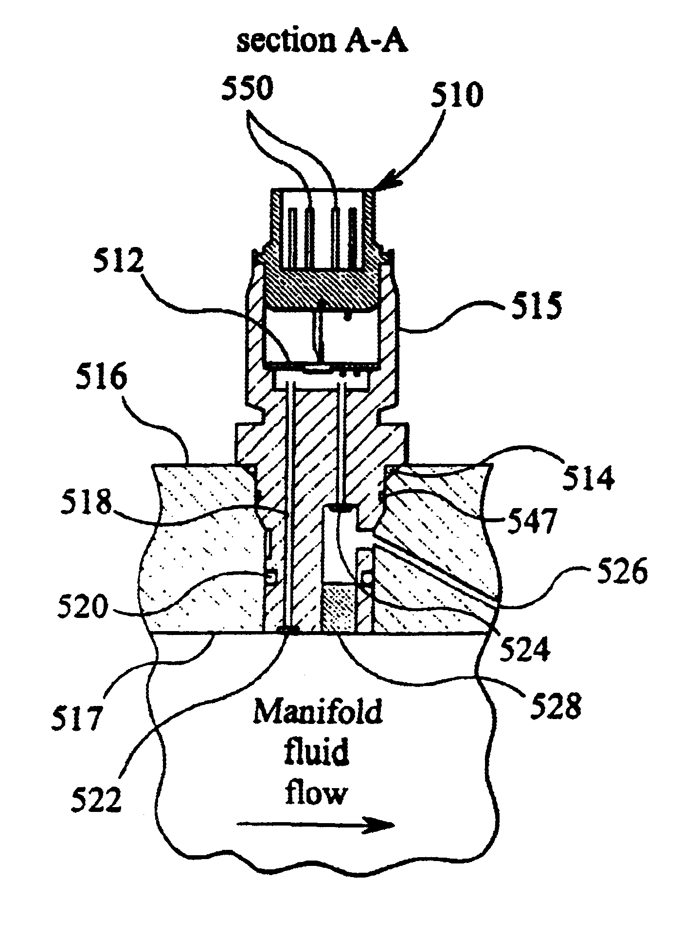
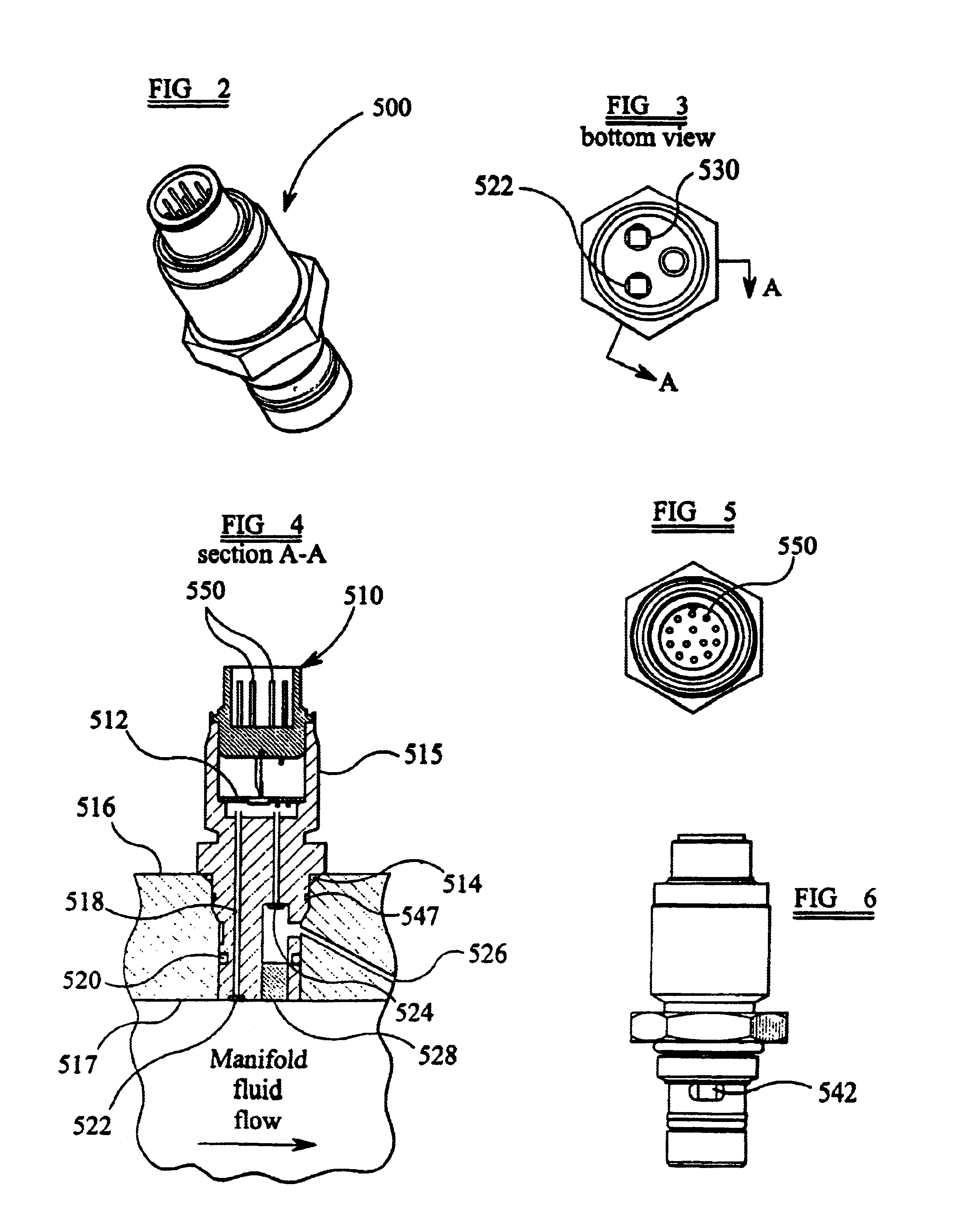
Embodiments of the present invention are directed to sensor components in which various MEMS sensors for measuring pressure, differential pressure, flow rate, temperature, pH level, viscosity, and / or moisture content of the fluid flow may be used. Multiple MEMS sensors may be arranged on a single chip to form a sensor package, and multiple sensor packages may be included in a single, unitary sensor component. The MEMS sensors may output real-time measurements or related data, thus allowing real time continuous monitoring of the fluid system. The measurements or data may be interpreted to predict when failure of the filter element will occur or to determine whether replacement of the filter element is necessary. In particular embodiments, MEMS sensor data may be used to detect the occurrence of undesirable events such as particle breakthrough or cavitation.

In addition to allowing real time continuous monitoring (as opposed to merely providing an indication at pre-set values), the pre...


PUM

PropertyMeasurementUnit
temperatureaaaaaaaaaa
pressureaaaaaaaaaa
flow rateaaaaaaaaaa

Abstract

A sensor component that may be used in conjunction with a filter module may include a plurality of sensor packages. The latter, in turn, may incorporate one or more micro-electromechanical systems (MEMS) sensors to measure various characteristics of fluid flow and filtration. A single sensor component may be adapted to measure the pressure, temperature, flow rate, differential pressure, conductivity, viscosity, pH level, etc. of the fluid at an upstream and a downstream location. Sensor measurements may be obtained continuously in order to monitor and indicate fluid conditions, including the use of a warning mechanism to indicate an out-of-range condition when the measurements fall outside of pre-set limits. Depending on the application and the fluid being filtered, data, including measurement data, may be transmitted through electrical connections or wirelessly. In wireless configurations, a sleep-mode may be included to maximize the life of local power supplies.

Description

FIELD OF INVENTIONThe present invention is directed to filtration systems incorporating micro-electromechanical systems (MEMS) to provide flow and filtration characteristic data.BACKGROUNDFilter modules have been used in a variety of applications and fluidic environments. When in service, it is often desirable to sense and measure various fluid flow and filter performance characteristics in order to determine whether a filter element within the filter module is performing within application specifications, and whether a filter element must be replaced or reconditioned before continuing operation.In typical filter modules, a filter element is encased within a filter body, or casing (e.g., a filter bowl), and between inlet and outlet end caps. A filter manifold(s) may be attached to the filter body to feed unfiltered medium to the upstream side of the filter element (e.g., where the filter element is cylindrical, the outside of the filter element). As the medium passes to the downstre...

Claims


Application Information

Patent Timeline
Patent Type & Authority Patents(United States)
IPC IPC(8): B01D35/14B01D35/143B01D29/60
CPCB01D29/603B01D35/143B01D29/606B01D29/608
Inventor MOSCARITOLO, DANIELSANDFORD, MICHAEL
Owner PTI TECH
Why Eureka
Try Eureka