Selective high-side and low-side current sensing in switching power supplies

a switching power supply and low-side current technology, applied in the direction of electric variable regulation, process and machine control, instruments, etc., can solve the problems of difficult objective of providing a fast pwm comparator, use of the conventional single-sensing scheme, and short sensing window

Active Publication Date: 2005-02-08
MICREL
View PDF1 Cites 106 Cited by
  • Summary
  • Abstract
  • Description
  • Claims
  • Application Information

AI Technical Summary

Benefits of technology

To implement the current sensing scheme of the present invention, the switching regulator further includes a first current sensing circuit for sensing a current through the first switch and providing a first current sense signal, and a second current sensing circuit for sensing a current through the second switch and providing a second current sense signal. The switching regulator also includes a control circuit for generating a first switch control signal and a second switch control signal for driving the first switch and the second switch respectively for generating the switch output voltage so as to maintain the regulated output voltage at a substantially constant magnitude. The control circuit generates the switch control signals in response to a selected one of the first and second current sense signals.
Finally, the switching regulator includes a duty cycle detection circuit coupled to determine a duty cycle of the switching regulator. The duty cycle detection circuit asserts a first select signal when the duty cycle exceeds a first threshold level and asserts a s

Problems solved by technology

A difficulty in the use of the conventional single-sensing scheme arises when the operating point of the switching regulator causes the current-sensing window to be very brief.
Not only is providing a fast PWM comparator a difficult objective, but such a comparator is typically noise sensitive and therefore not desirable.
Consequently, there are increasing numbers of situations in which the duty cycle of a step down switching power supplies will approach zero, making high-side current sensing difficult.
However, using low-side sensing results in the same sort of problem at the opposite extreme in duty cycle where the duty cycle is very high.
In the high duty cycle condition, sensing at the low-side switch becomes difficult.
Therefore, no matter whether such supplies sense current through the high-side or low-side switch, the power supplies must operate in a regime where duty cycle control is difficult due to short sensing window.
Co

Method used


Image

  • Selective high-side and low-side current sensing in switching power supplies
  • Selective high-side and low-side current sensing in switching power supplies
  • Selective high-side and low-side current sensing in switching power supplies

Examples


Embodiment Construction

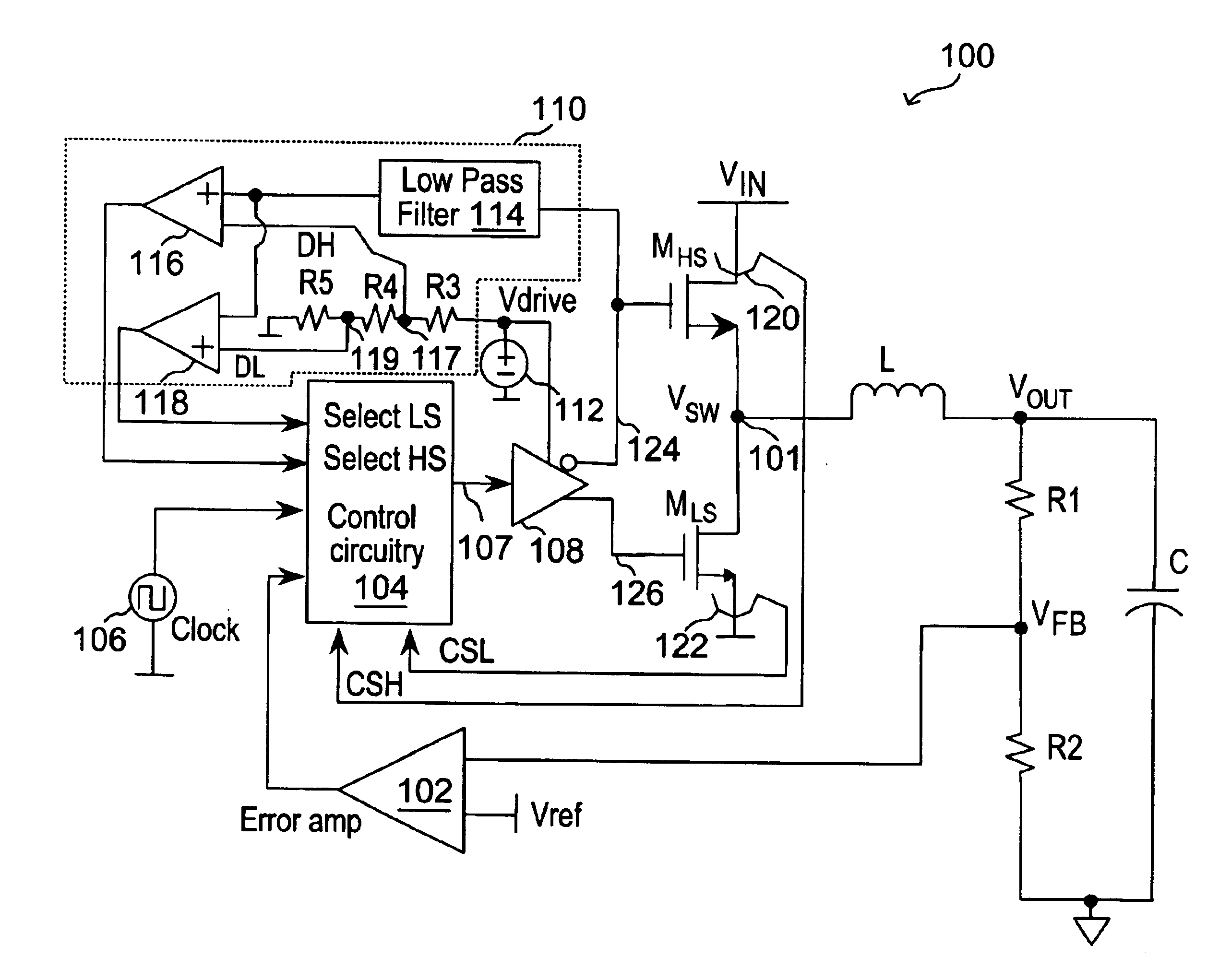
In accordance with the principles of the present invention, a current mode switching regulator employs selective current sensing whereby high-side current sensing and low-side current sensing are both provided and depending on the prevailing duty cycle, the current sense signal with the longer sense window is selected. The selection of the current sense signal in turn enables the switching regulator to assert peak or valley control of the duty cycle. In this manner, effective current mode control is realized as an adequate sensing window is always ensured despite changing operation conditions. In one embodiment, a switching regulator performs current sensing at the energy storage element (such as an inductor) and the current sense signal for the increasing or the decreasing current phase is selected based on the duty cycle to assert peak or valley control of the duty cycle.

In the present description, “duty cycle” is defined as the percentage of time within a system clock period a sw...


PUM


Abstract

A current mode switching regulator implementing a dual sense scheme includes a first current sensing circuit for sensing a current through a first switch and providing a first current sense signal, and a second current sensing circuit for sensing a current through a second switch and providing a second current sense signal. The switching regulator includes a control circuit for generating switch control signals for driving the first and second switches in response to one of the first and second current sense signals. The regulator further includes a duty cycle detection circuit coupled to determine a duty cycle of the switching regulator. The detection circuit asserts a first select signal to select the first current sense signal when the duty cycle exceeds a first threshold level and asserts a second select signal to select the second current sense signal when the duty cycle is less than a second threshold level.

Description

FIELD OF THE INVENTIONThe invention relates to switching power supplies or switching regulators and, in particular, to a switching regulator employing selective current sensing to assert either peak or valley control.DESCRIPTION OF THE RELATED ARTA switching regulator, also referred to as a switching mode power supply, provides power supply function through low loss components such as capacitors, inductors, and transformers, and power switches that are turned on and off to transfer energy from the input to the output in discrete packets. A feedback control circuit is used to regulate the energy transfer to maintain a constant output voltage within certain load limits of the circuit.A common technique used in the feedback control is pulse-width modulation (PWM). That is, the output voltage VOUT of the switching regulator is regulated by controlling the duty cycle (or by varying the pulse width) of the rectangular switch voltage VSW applied to the inductor and the capacitor of the out...

Claims


Application Information

Patent Timeline
IPC IPC(8): H02M3/158H02M3/04
CPCH02M3/1588Y02B70/1466H02M2001/0009H02M1/0009Y02B70/10
Inventor INN, BRUCE L.
Owner MICREL
Why Eureka
Try Eureka