Magnetic field measurement system

a measurement system and magnetic field technology, applied in the direction of magnetic field measurement using superconductive devices, instruments, applications, etc., can solve the problems of difficult to determine three factors, disadvantageous system scale, and difficult to determine three or more factors that should be corrected, etc., to achieve efficient measurement

Active Publication Date: 2005-02-08
HITACHI LTD
View PDF2 Cites 24 Cited by
  • Summary
  • Abstract
  • Description
  • Claims
  • Application Information

AI Technical Summary

Benefits of technology

With the foregoing structures, it becomes possible to efficiently obtain a measurement signal under less influence of the extern...

Problems solved by technology

Although Prior Art 1 has performed the process of multiplying, by the three different factors, the x-, y-, and z-components of the external field sensed by using the vector magnetometer and subtracting the result of multiplication from the output signal from the magnetometer for biomagnetic signal measurement, it has the problem that the three factors are difficult to determine and the scale of the system is increased disadvantageously becaus...

Method used


Image

  • Magnetic field measurement system
  • Magnetic field measurement system
  • Magnetic field measurement system

Examples


embodiment 1

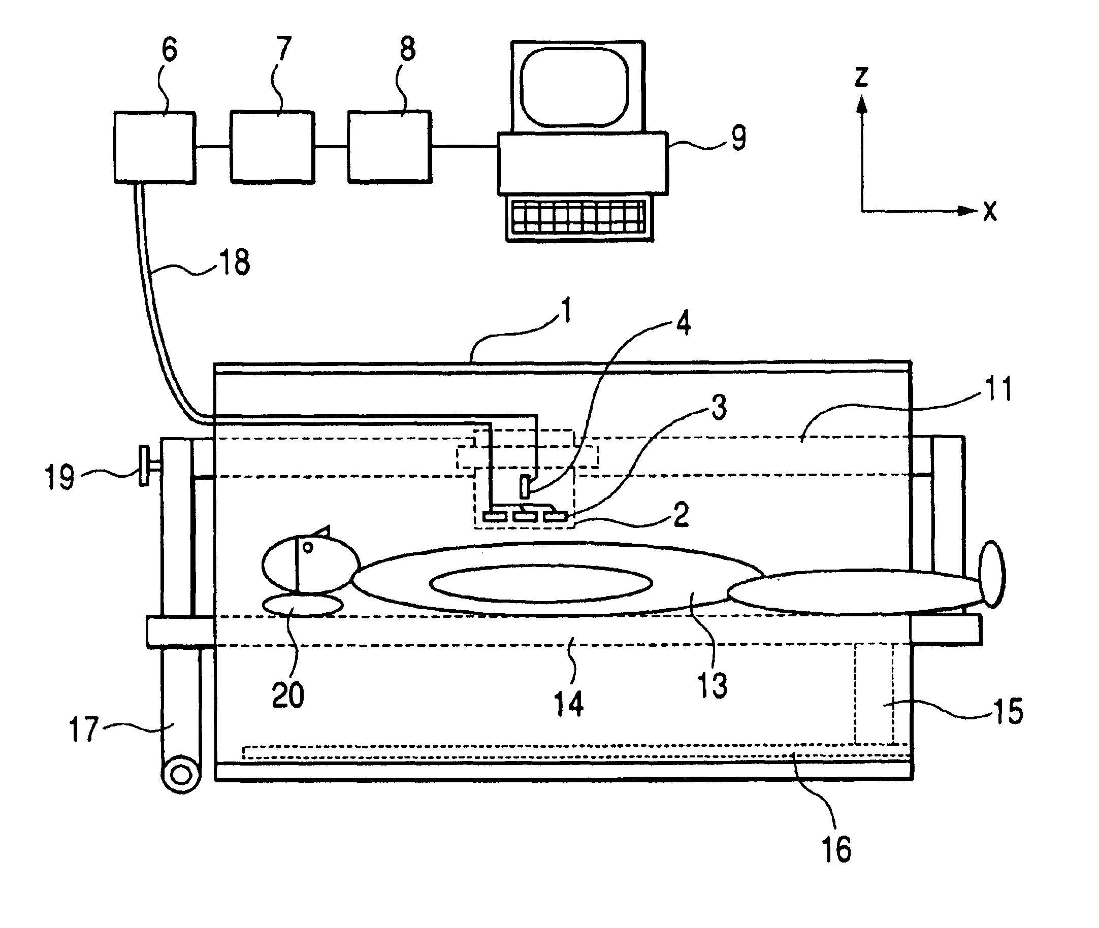
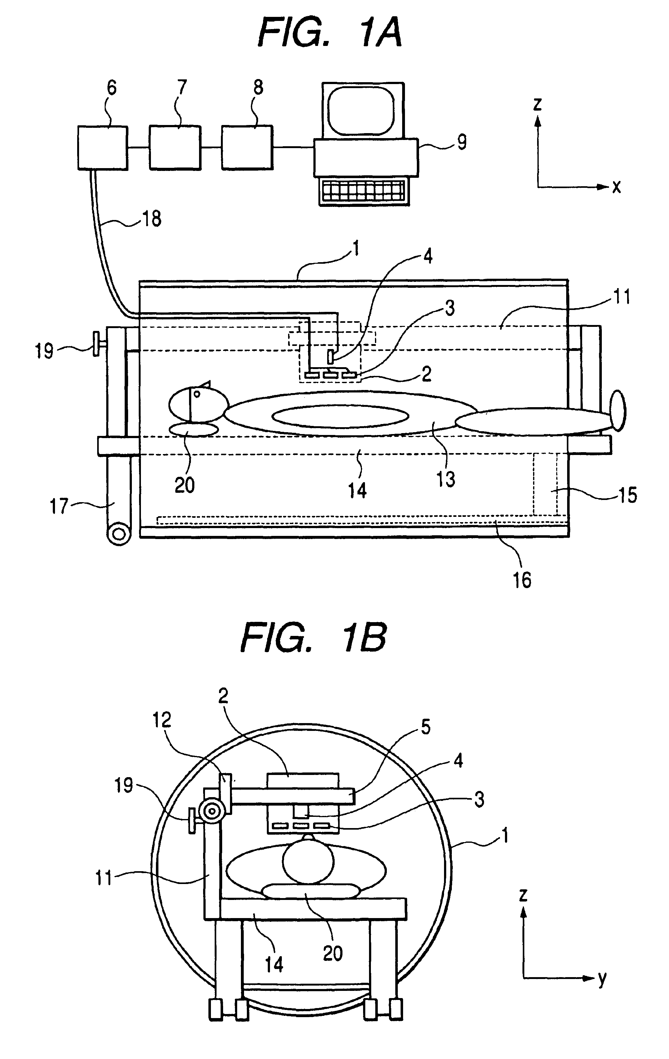
FIGS. 1 are views each showing an example of a structure of a magnetic field measurement system according a first embodiment of the present invention, which is a magnetocardiographic measurement system using a cylindrical magnetic shield. It is assumed that the center axis of the cylindrical magnetic shield 1 is an x-axis and two axes orthogonal to the x-axis are y- and z-axes. Of FIGS. 1, FIG. 1A is an x-z cross sectional view and FIG. 1B is a y-z cross sectional view.

In the transversely mounted cylindrical magnetic shield 1, a bed 14 on which a subject 13 lies down in a recumbent position with his or her head supported by a pillow 20 and a dewar 2 are disposed. A plurality of sensing magnetometers 3 and a first reference magnetometer 4 are disposed on the inner bottom portion of the dewar 2 and cooled with a cryogen. The first embodiment has used the magnetometers each composed of a high critical temperature superconductor operable at a liquid nitrogen temperature and cooled the m...

embodiment 2

The magnitude of an external field greatly depends on the location at which the system is placed. The external field largely fluctuates at a location closer to, e.g., a railroad track or an elevator.

FIGS. 6 are views showing examples of magneto-cardiograms obtained from measurement using a magnetic field measurement system according to a second embodiment of the present invention, of which FIG. 6A shows magnetic field signals when external field correction according to the second embodiment has not been performed and FIG. 6B shows magnetic field signals when the external field correction according to the second embodiment has been performed.

FIG. 6A shows the waveforms of output signals (B(1, 1), B(2, 1)) from the sensing magnetometers when measurement was performed by placing a magnetocardiograph (magnetic field measurement system) inside a building positioned at a distance of about 30 m from a train track. The band was in the range of 0.1 Hz to 80 Hz and analog notch filters of 50,...

embodiment 3

When magnetocardiographic measurement was performed by using the system of the structure according to the first embodiment, it was proved that noise at a frequency of about several hertz remained in some cases depending on the place where the system is disposed.

FIG. 7 is a view showing examples of magnetocardiograms obtained from measurement using the magnetic field measurement system according to a third embodiment of the present invention. The magnetic field signal in the uppermost portion of FIG. 7 represents the difference data X(1, 1) before external field correction was performed. The magnetic field signal in the middle portion of FIG. 7 represents the difference data Cx(1, 1) after correction using the first reference signal was performed. Although the large fluctuations induced by the external field have been removed by performing the correction using the first reference signal described in the first embodiment, a small oscillation component of about 5 Hz remains at each of ...


PUM


Abstract

A magnetic field measurement system for canceling an external field is provided, in which plurality of sensing magnetometers (3) for measuring a magnetic field signal in a direction perpendicular to the center axis of a cylindrical magnetic shield (1) are arranged in two dimensions on a plane parallel to the center axis and a reference magnetometer (4) for measuring the external field parallel to the center axis as a reference signal is disposed on a plane perpendicular to the plane parallel to the center axis. The reference signal multiplied by a specified factor is subtracted from a difference between signals from the adjacent sensing magnetometers (3). The magnetic field measurement system allows measurement of an extremely weak magnetic field by efficiently canceling the external field.

Description

CLAIM OF PRIORITYThe present application claims priority from Japanese application JP 2003-139754 filed on May 19, 2003, the content of which is hereby incorporated by reference into this application.FIELD OF THE INVENTIONThe present invention relates to a magnetic field measurement system for measuring a magnetic field generated from a measurement target, e.g., an extremely weak magnetic field generated from the heart, brain, or the like of a living body by using a magnetometer employing a high-sensitivity superconducting quantum interference device (SQUID) and, more particularly, to a magnetic field measurement system for canceling an external field.BACKGROUND OF THE INVENTIONA magnetic field measurement system employing a SQUID has been used conventionally to measure a magnetic field (hereinafter referred to as a biomagnetic signal) generated from the brain, heart, or the like of a living body. In the measurement of an extremely weak magnetic field such as a biomagnetic signal, i...

Claims


Application Information

Patent Timeline
IPC IPC(8): G01R33/035G01R33/025A61B5/05
CPCG01R33/0358G01R33/025
Inventor TSUKAMOTO, AKIRAYOKOSAWA, KOICHISUZUKI, DAISUKEKANDORI, AKIHIKOTSUKADA, KEIJI
Owner HITACHI LTD
Why Eureka
Try Eureka