Controller for generating a periodic signal with an adjustable duty cycle

a controller and duty cycle technology, applied in pulse generators, pulse manipulation, pulse widths, etc., can solve the problems of signal and input control voltage representing loop errors, affecting the operation of pulse widths, etc., to achieve the effect of reducing operating current, retaining stability and linear performance, and maintaining high precision

Inactive Publication Date: 2005-02-08
ABB INC
View PDF38 Cites 37 Cited by
  • Summary
  • Abstract
  • Description
  • Claims
  • Application Information

AI Technical Summary

Benefits of technology

It is therefore an object of the present invention to provide a continuously adjustable duty cycle controller that uses only one operational amplifier and no more than three CMOS logic elements, which reduces operating current, employs a novel cascode current source permitting operation on a low voltage single power supply, maintains high precision over a wide range of duty cycles through the use of a high gain servo integrator and its associated feedback and filtering circuitry, and retains stability and linear performance when presented with a variable duty cycle ratio controlling signal that may reach zero volts.
It is a further object of this invention to provide a duty cycle controller with at least two clock outputs that can be used together to achieve a time delay function that affords a differential delay range from zero nanoseconds to several thousand nanoseconds.

Problems solved by technology

Unfortunately, this is only useful for pulse widths down to tenths of a microsecond.
The difference between the feedback signal and the input control voltage represents the loop error.
However, using a non-zero control voltage can also effect a constant inter-channel time delay.
In this case, however, no provision is made for an external duty cycle ratio control input.
The disclosed circuits employ several (more than three) digital elements, all of which toggle at the reference clock frequency leading to substantial current consumption at higher (>1 MHz) clock frequencies.
To achieve significant delays, however, a shallower wave front is required, necessitating more low pass filtering.
Such additional filtering also reduces the overall amplitude of the low pass filtered waveform that is presented to the detector as a timing signal; for applications wherein significantly more delay may be required, the amount of filtering required would inevitably yield a waveform too small for reliable detection.
The dominant pole of the very high gain operational amplifier will add to that of the integrator (which itself has very high gain at low frequencies), leading to a potentially unstable system, especially for wide duty cycle ratios at lower clock frequencies.
Furthermore, the equivalent input noise of the open loop operational amplifier is not suppressed by any local feedback, and will lead to excessive noise at its output with correspondingly increased timing jitter in the duty cycle ratio.
Finally, whenever the input control voltage signal descends to a value corresponding to a sub-minimum pulse width (i.e., requiring a duty cycle having a positive pulse duration less than the sum of the reset time for the capacitor plus the time required for the capacitor's voltage to slew from ground to the detector threshold level), the output of the open loop operational amplifier will saturate at ground, leading to severely non-linear duty cycle performance during the early part of the ramp as a result of the protracted recovery period.

Method used


Image

  • Controller for generating a periodic signal with an adjustable duty cycle
  • Controller for generating a periodic signal with an adjustable duty cycle
  • Controller for generating a periodic signal with an adjustable duty cycle

Examples


Embodiment Construction

Throughout the appended drawings, the same reference numbers are used to designate the same or similar components.

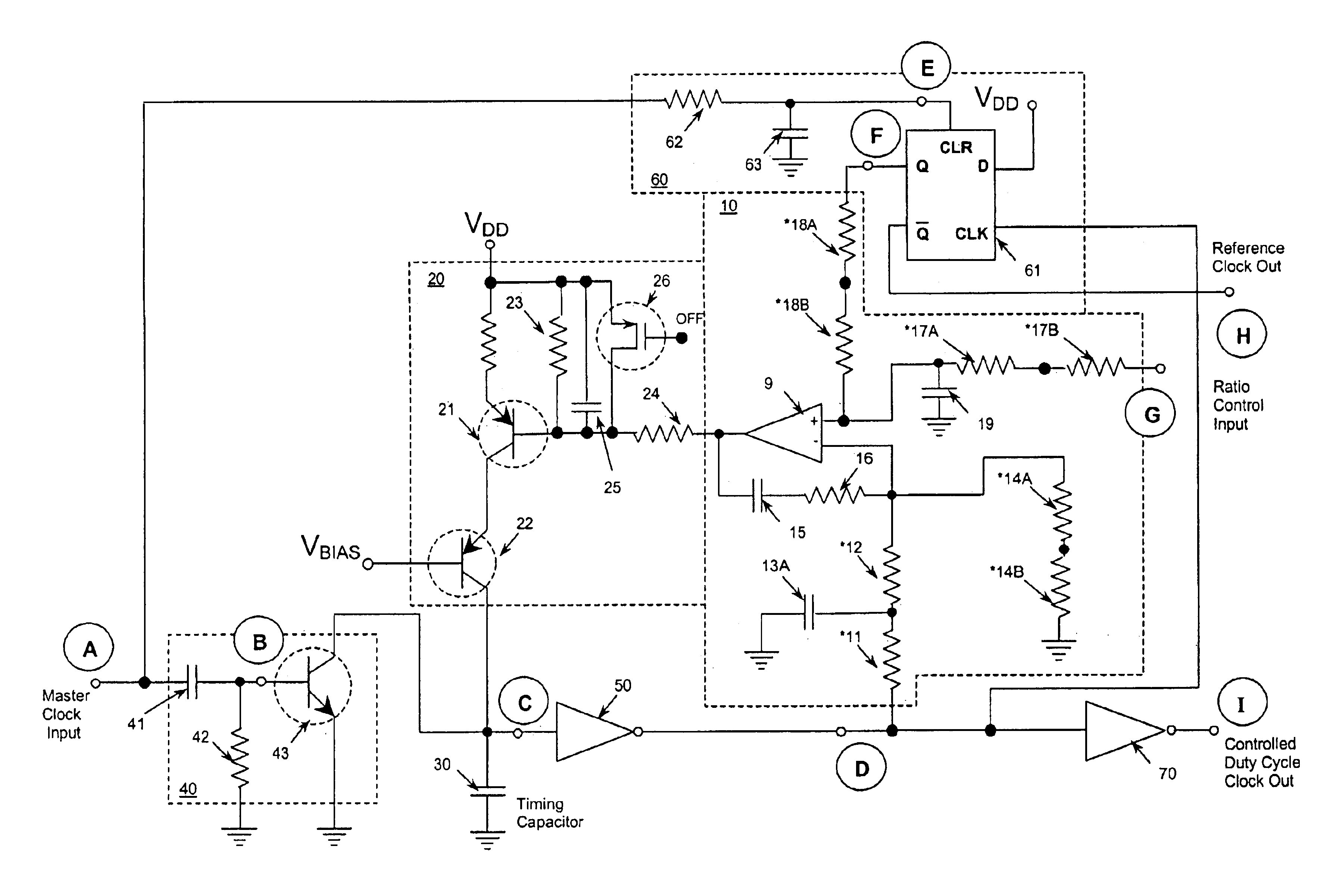
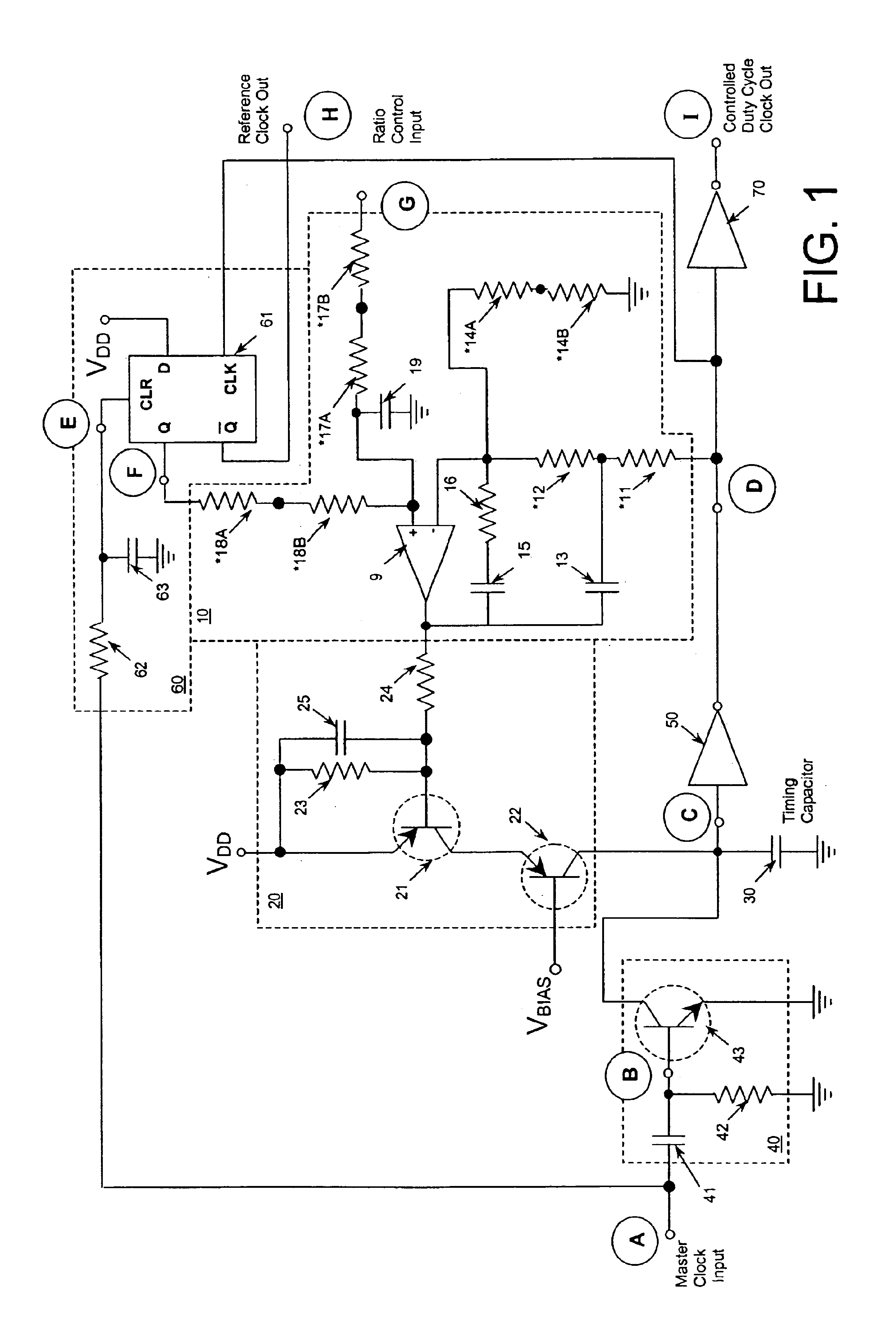
Reference is made first to FIG. 1 for a description of the basic circuit structure and function for the present invention. FIG. 1 illustrates the arrangement of a pulse width controlled duty cycle generator according to the present invention. The basic elements of the circuit include integrator 10, voltage controlled current source 20, capacitor 30, reset switch 40, invert gate 50, reference pulse generator 60, and output clock buffer 70. During normal operation, while this circuit is providing controlled width output pulses at nodes D and I, the inputs presented to integrator 10 are sufficient to ensure that its output voltage keeps voltage controlled current source 20 properly biased and capable of supplying some level of output current to timing capacitor 30.

Reset switch 40 is composed of a high frequency NPN transistor 43 (such as an AT-30533 HP device), that is brie...


PUM


Abstract

A controller that is linearly responsive to an input voltage provides continuously adjustable control of the width of a periodically repeating digital pulse, thereby achieving a linear voltage to duty-cycle ratio transfer function. The circuit of the present invention includes a master clock input, a ratio control voltage input, a controlled duty cycle clock output, a high gain amplifier configured as an integrator having differential inputs, each equipped with a low pass filter, a controlled current source, a resettable timing capacitor, a threshold detector and a reference pulse generator.

Description

BACKGROUND OF THE INVENTION1. Field of the InventionThe present invention relates generally to electronic circuits for generating periodic output signals. The present invention relates more specifically to an electronic circuit that allows linear voltage control of the width of a periodically repeating digital pulse, and therefore provides continuously variable duty cycle ratio control of an output clock signal that is synchronous with an input clock signal.2. Description of the Related ArtOne of the most useful electronic circuits is one that generates a digital (a periodic on-off) signal for controlling the operation of one or more digital or digitally controllable devices. It is most useful when the ratio of the on-time during each cycle to the off-time of the cycle, that is, the duty cycle ratio, can be easily varied and controlled. In some embodiments of the basic controller circuit, the linear variance of an analog device, that might for example provide an adjustable voltage, ...

Claims


Application Information

Patent Timeline
Patent Type & Authority Patents(United States)
IPC IPC(8): H03K5/06H03K5/156H03K5/04
CPCH03K5/06H03K5/1565H03K5/135
Inventor LALETIN, WILLIAM H.
Owner ABB INC
Why Eureka
Try Eureka