Monopulse radar system

a radar system and monopulse technology, applied in direction finders using radio waves, instruments, reradiation, etc., can solve the problem that the azimuth of a detected body cannot be detected

Inactive Publication Date: 2005-02-08
HITACHI LTD
View PDF17 Cites 46 Cited by
  • Summary
  • Abstract
  • Description
  • Claims
  • Application Information

AI Technical Summary

Benefits of technology

Therefore, the invention is made to solve the problem and it is the object to provide a low-cost, compact and light monopulse radar system wherein the monopulse system is improved, a detectable range of the position (distance betwee...

Problems solved by technology

Hei 2-287181, “RADAR SYSTEM USED FOR CAR”) is known, however, according to...

Method used


Image

  • Monopulse radar system
  • Monopulse radar system
  • Monopulse radar system

Examples


third embodiment

FIG. 4 is a block diagram showing the configuration of the radar system according to the invention. A monopulse radar system used for a car equivalent to this embodiment is characterized in that an antenna beam shape is switched by only a receiving antenna, the configuration and the control of a transmitting antenna are simplified, the system is simplified and the cost is reduced.

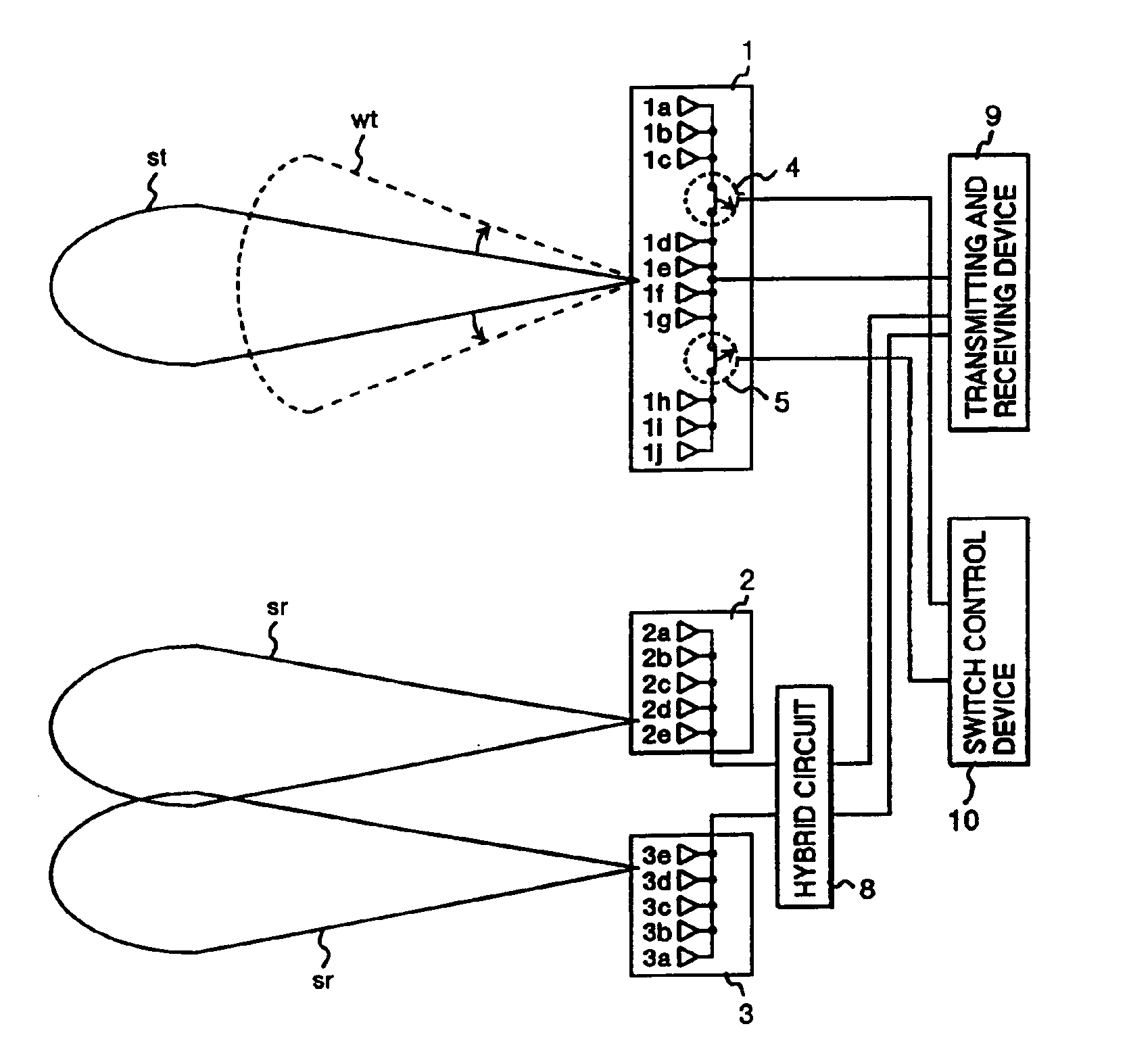
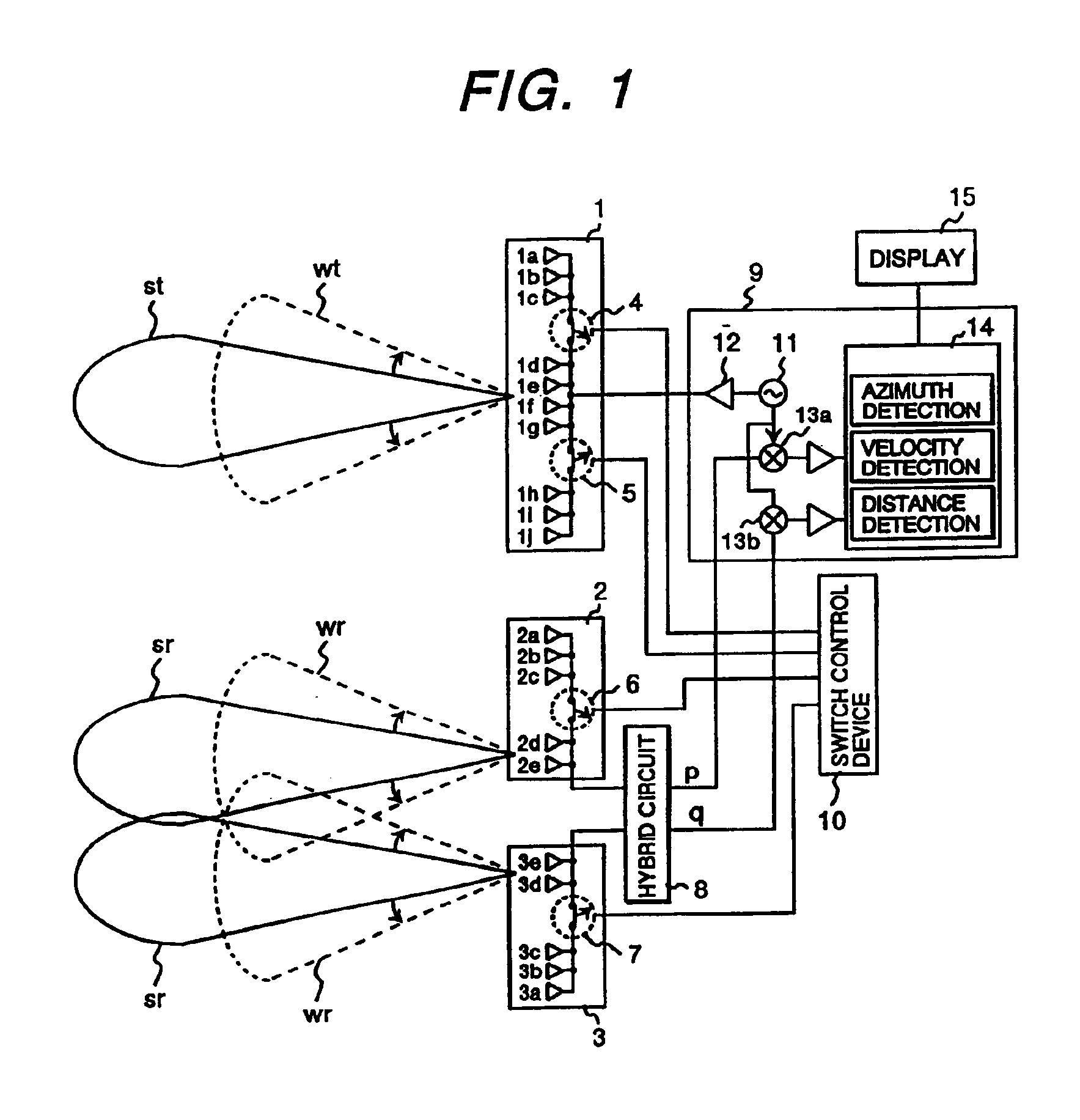
A signal is transmitted from a transmitting and receiving device 9 via a transmitting array antenna 1 composed of plural antenna elements 1a to 1j, the signal reflected on an obstacle is received by a receiving array antenna 2 composed of plural antenna elements 2a to 2e and a receiving array antenna 3 composed of plural antenna elements 3a to 3e, a sum signal and a difference signal respectively generated in a hybrid circuit 8 are sent to the transmitting and receiving device 9, and the velocity of a mobile body, the direction of an obstacle, distance up to the mobile body and relative velocity are detecte...

fourth embodiment

FIG. 5 is a block diagram showing the configuration of the radar system according to the invention. A monopulse radar system used for a car equivalent to this embodiment is characterized in that the system is simplified and the cost is reduced by sharing a transmitting antenna and a receiving antenna.

A signal is transmitted or received via the transmitting and receiving common array antennas 11 and 12 respectively composed of plural antenna elements 11a to 11e and 12a to 12e by a transmitting and receiving device 9, and the velocity of a mobile body, the direction of an obstacle, distance up to the mobile body and relative velocity are detected by a sum signal and a difference signal respectively generated in a hybrid circuit 8. In this radar system, antenna switches 6 and 7 for connecting and disconnecting antenna element groups respectively composed of the plural antenna elements 11a to 11c and 12a to 12c for switching a beam shape from / to the transmitting and receiving common arr...


PUM


Abstract

A monopulse radar system for detecting an azimuth depending upon amplitude difference or phase difference between signals respectively received by plural receiving antennas, includes: a transmitting array antenna and a receiving array antenna each including antenna elements forming an antenna train, at least one antenna switch disposed among the elements of the transmitting array antenna and/or the receiving array antenna, and a switch controller for turning ON/OFF the antenna switch to change an aperture length of the transmitting array antenna and/or the receiving array antenna thereby changing a beam shape thereof. The antenna elements of the transmitting array antenna and the receiving array antenna are formed on a dielectric substrate. A dielectric length between the antenna train formed by the antenna elements and the antenna switch is ½ dielectric wavelength.

Description

FIELD OF THE INVENTIONThe present invention relates to a monopulse radar system, further detailedly relates to a monopulse radar system that radiates a radio wave, receives a reflected radio wave from a body where the radio wave is detected with plural receiving antennas and detects the direction of the detected body depending upon difference in amplitude or a phase between signals received by the plural receiving antennas and particularly relates to a monopulse radar system suitable for a radar used for a car and mounted on a mobile body such as a vehicle.DESCRIPTION OF THE RELATED ARTSHeretofore, a radar system used for a car and mounted on a mobile body such as a vehicle for detecting the velocity and the position of a detected body such as the mobile body and an obstacle is known. For a radar system used for a car, a radar system used for a car in which antenna beam width is switched from wide one to narrow one and vice versa corresponding to a detected body and the velocity and...

Claims


Application Information

Patent Timeline
IPC IPC(8): G01S13/00G01S13/44H01Q25/00G01S13/93G01S3/14G01S3/46G01S13/931H01Q1/32H01Q3/26H01Q25/02
CPCG01S13/4463H01Q3/2605H01Q25/002H01Q25/02H01Q1/3233G01S3/46G01S13/003G01S13/931G01S2013/9353G01S2013/932
Inventor SHINODA, HIROSHIKONDOH, HIROSHI
Owner HITACHI LTD
Why Eureka
Try Eureka