Inverse precision velocity update for monopulse calibration

a technology of precision velocity and calibration, applied in the direction of instruments, measurement devices, using reradiation, etc., can solve the problems of bias errors, inability to accurately measure the angle of a monopulse to a target, and the complex process of the sar process for moving targets

Active Publication Date: 2005-02-08
RAYTHEON CO
View PDF6 Cites 30 Cited by
  • Summary
  • Abstract
  • Description
  • Claims
  • Application Information

AI Technical Summary

Problems solved by technology

The SAR process becomes more intricate for moving targets.
The accuracy of these angle measurements is often limited by bias errors internal to the radar which are not related to the signal to noise ratio of the received radar return.
In effect, the bias errors preclude accurate monopulse angle measurement to a target, even if the target is clearly visible by the radar.
One cause of these bias errors is the presence of the radome in the path of both the transmitted and the received radar signal.
Another cause of bias errors comes from imbalances in the antenna/receiver syst...

Method used


Image

  • Inverse precision velocity update for monopulse calibration
  • Inverse precision velocity update for monopulse calibration
  • Inverse precision velocity update for monopulse calibration

Examples


Embodiment Construction

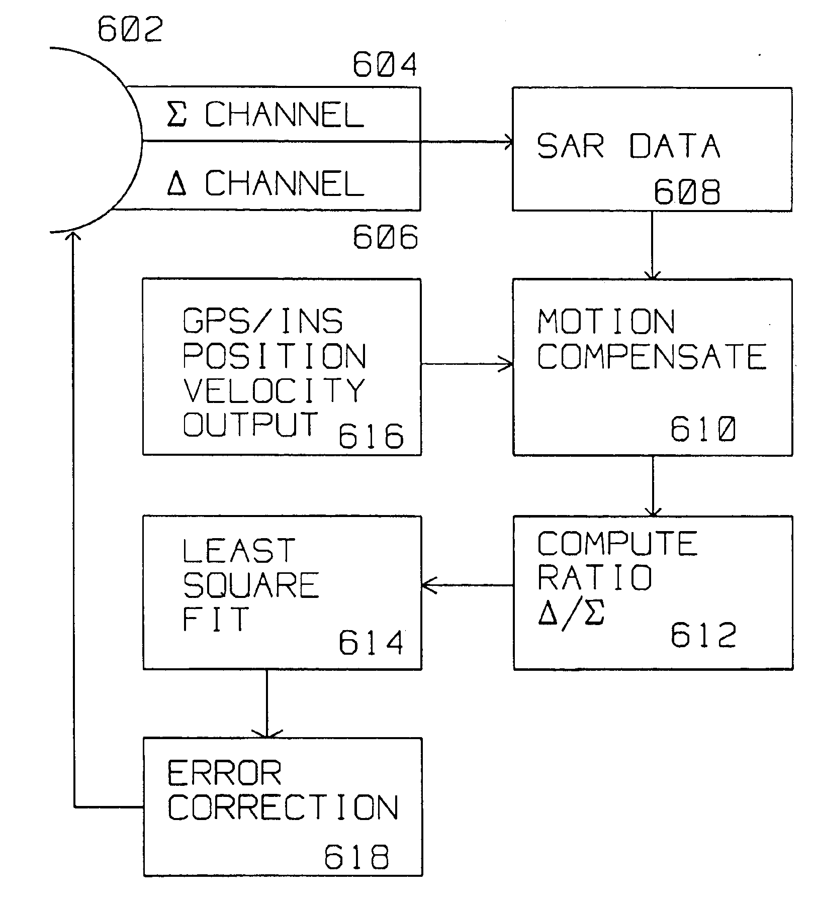
The present invention describes an apparatus and method of removing bias an radome errors associated with monopulse measurements that reduces the need for a monopulse angle calibration table by using SAR imagery to estimate elevation and azimuth angle errors directly.

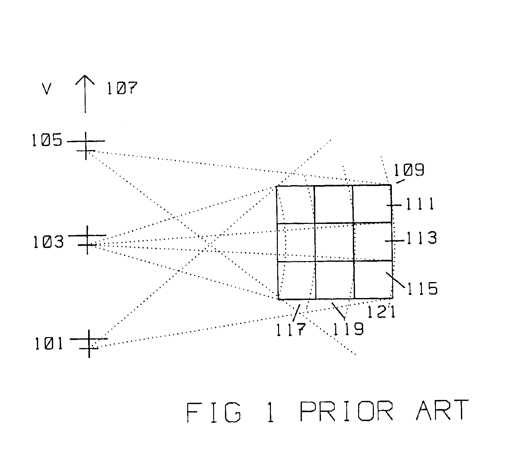
FIG. 1, the prior art, shows a simplified, typical geometric relationship between a moving platform carrying a radar transmitter / receiver using Synthetic Aperture (SAR) methods and target area 109 to be imaged by said radar transmitter / receiver. The moving platform is initially at position 101, travels with velocity V in the direction 107. The moving platform moves from position 101 to position 103, and then to position 105 along a path in direction 107. Imaging pulses are transmitted and received at each position 101, position 103 and position 105. At position 103 for example, the target area 109 to be imaged falls within range bins 117, 119, and 121. In azimuth, target area 109 falls within azimuth positions 111, ...


PUM


Abstract

A radar system derives a correction for an actual boresight (311) of a radar monopulse antenna mounted on a moving platform from Σ data and Δ data generated with respect to an a priori known, calibrated boresight (309). The monopulse antenna (602) is coupled to a ground position measuring system (616) while acquiring data. The radar receiver acquires a Σ and Δ synthetic aperture map of the same radar scattering location with respect to the calibrated boresight. Σ SAR data and the Δ SAR data are motion compensated using the position and velocity supplied by the ground positioning system. A computer forms a ratio of the aligned Δ pixels to the aligned Σ pixels for each of a plurality of aligned Σ pixels located near the calibrated boresight. The correction for the location of the actual boresight of the monopulse antenna is computed by an analysis of the ratio of aligned Σ pixels and corresponding aligned Δ pixels over the radar scattering location. Typically, a least square fit analysis is used to plot the Δ/Σ ratio, and ascertain where the zero crossing of the monopulse angle=0 line is found thereby identifying the position of the actual boresight, and the correction from the a priori, calibrated boresight.

Description

BACKGROUND OF THE INVENTION1. Field of InventionThis invention is in the field of radar antenna boresight orientation.2. Description of the Related ArtAn important function of a radar system, whether a Real Beam type, Synthetic Aperture (SAR) or Interferometric SAR is to detect a target as well as identify it. Radar target detection and identification have been proven necessary in military surveillance, reconnaissance, and combat missions. The detection and identification of targets provide real-time assessment of the number and the locations of targets of interest.One method of target detection and identification is to process the image acquired by the radar using, for example, Synthetic Aperture Radar (SAR) technology. By processing a SAR generated image, the features of a target can be extracted and matched to a database for identification.The general principle behind SAR is to obtain high resolution images by coherently combining the amplitude and phase information of separate r...

Claims


Application Information

Patent Timeline
IPC IPC(8): G01S13/00G01S13/90G01S7/40
CPCG01S7/4026G01S13/9023G01S2007/403G01S2007/4091G01S2007/4034G01S7/52004G01S13/9092G01S7/403G01S7/4034G01S7/4091
Inventor KRIKORIAN, KAPRIEL V.ROSEN, ROBERT A.
Owner RAYTHEON CO
Why Eureka
Try Eureka