

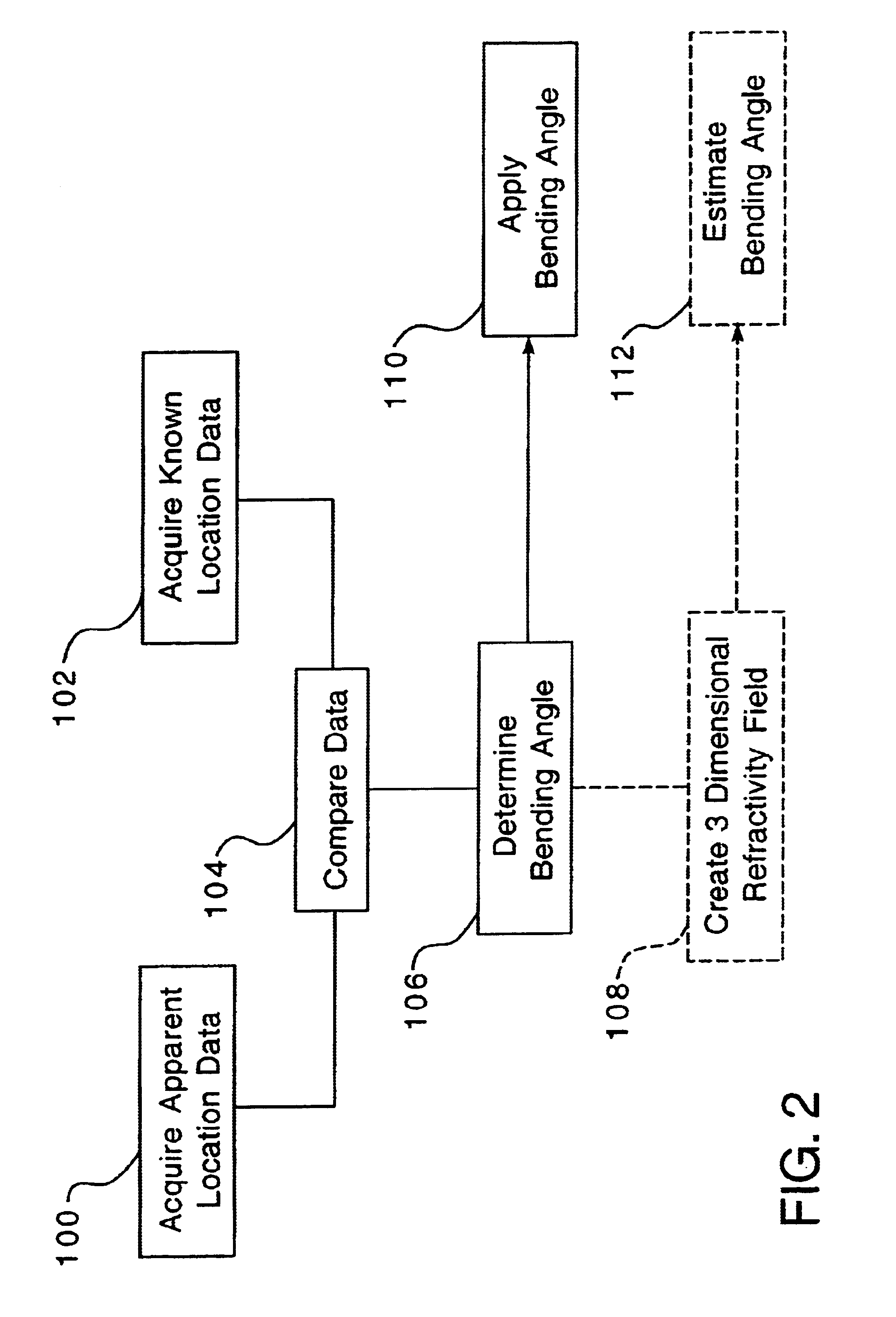
Method of compensating for atmospheric effects while using near horizon radar utilizing a Doppler signal
a near-horizon radar and doppler signal technology, applied in the field of methods, can solve the problems of only updating national weather service data once, significant degree of object error, and inability to meet the needs of the weather service, so as to reduce the refraction error
- Summary
- Abstract
- Description
- Claims
- Application Information
AI Technical Summary
Benefits of technology
Problems solved by technology
Method used
Image

Examples
Embodiment Construction
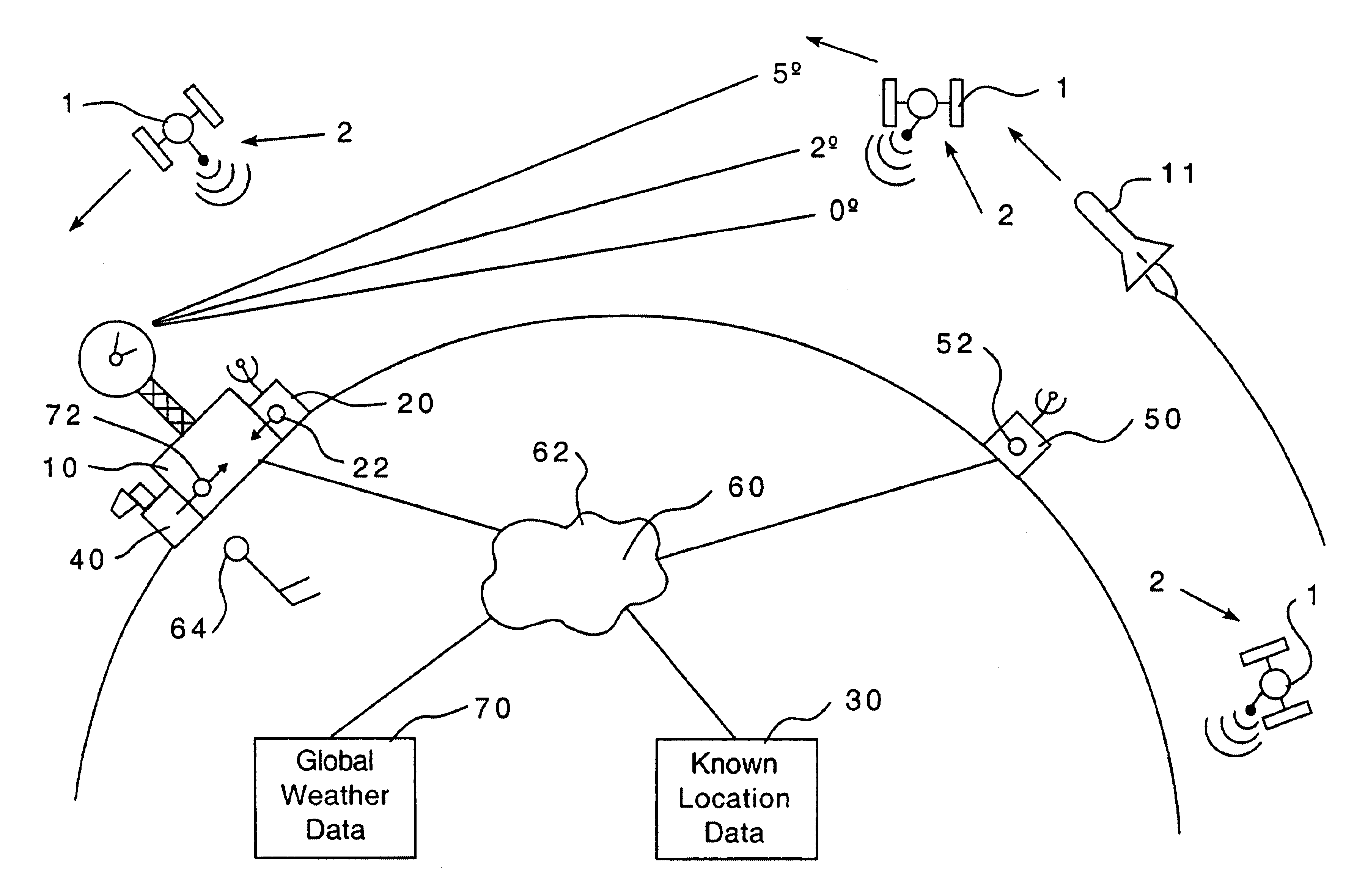
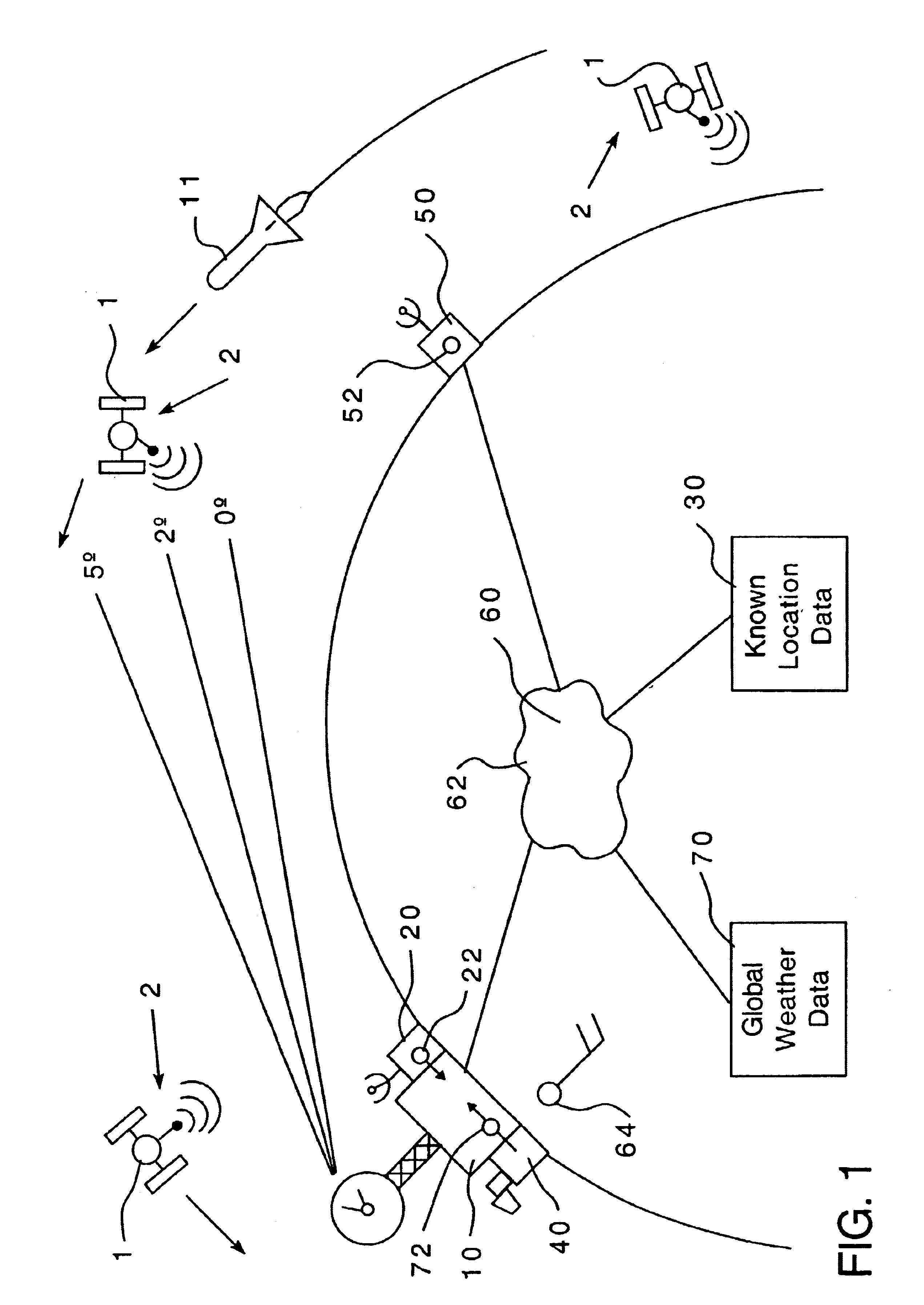
As used herein, “elevation” shall mean the angle of an object above the horizon relative to an observer and does not refer to the altitude of an object above the surface of the earth. Thus, an object may have an altitude many kilometers above the earth and still have a low “elevation” as seen from a distant site.
As used herein, “low elevation” shall mean an elevation between about 0° and 14°, where 0° is a line tangent to the horizon.
As used herein, “high elevation” shall mean an elevation between 15° and 90° where an object at 90° is directly overhead.
As used herein “actual location” shall mean the true location of an object.
As used herein “known location” shall mean the location of a satellite, such as a GPS satellite, based upon the most recently available data. Typically, the known location is the best estimation of the actual location of a satellite.
As used herein “observed location” shall mean the location of an object seen at a high elevation. That is, the observed location o...
PUM
 Abstract
Description
Claims
Application Information