Magnetically coupled tire pressure sensing system

a tire pressure sensing and magnetic coupling technology, applied in the direction of fluid pressure measurement, fluid pressure measurement using inductance variation, instruments, etc., can solve the problem of periodic need to dismount tires to replace batteries, inability to detect anomalous pressure in all tires, etc., and achieve the effect of low cos

Active Publication Date: 2005-02-15
BURNS ALAN ALEXANDER
View PDF24 Cites 32 Cited by
  • Summary
  • Abstract
  • Description
  • Claims
  • Application Information

AI Technical Summary

Benefits of technology

Accordingly, objects and advantages of the present invention are:(a) to provide a passive means from within a vehicle tire for reporting pressure;(b) to provide a continuous reading of tire pressure;(c) to provide a tire pressure reporting system with an indefinite lifetime;(d) to eliminate any need for batteries within tires;(e) to eliminate any need for power generation within tires:(f) to eliminate any need for sources transmitting power into tires;(g) to provide a low cost means for reporting tire pressure;(h) to provide a compact and lightwe

Problems solved by technology

The advantage is passive operation with no in-tire components but the disadvantage is the inability to detect anomalous pressure in all tires.
While this permits sensing the pressure in all tires, the in-tire unit is relatively large due to the requirement for a battery.
Another disadvantage is the periodic need to dismount tires to replace batteries.
However, this system has the disadvantage of requiring coaxial alignment between the sender and receiver, at least once per wheel rotation, which limits location possibilities for both the sender and the reader.
However, this system does not meet the requirements for an in-dash pressure display.
These types of device typically share the same problems as the other devices that depen

Method used


Image

  • Magnetically coupled tire pressure sensing system
  • Magnetically coupled tire pressure sensing system
  • Magnetically coupled tire pressure sensing system

Examples


Embodiment Construction

of the Tire Pressure Sender

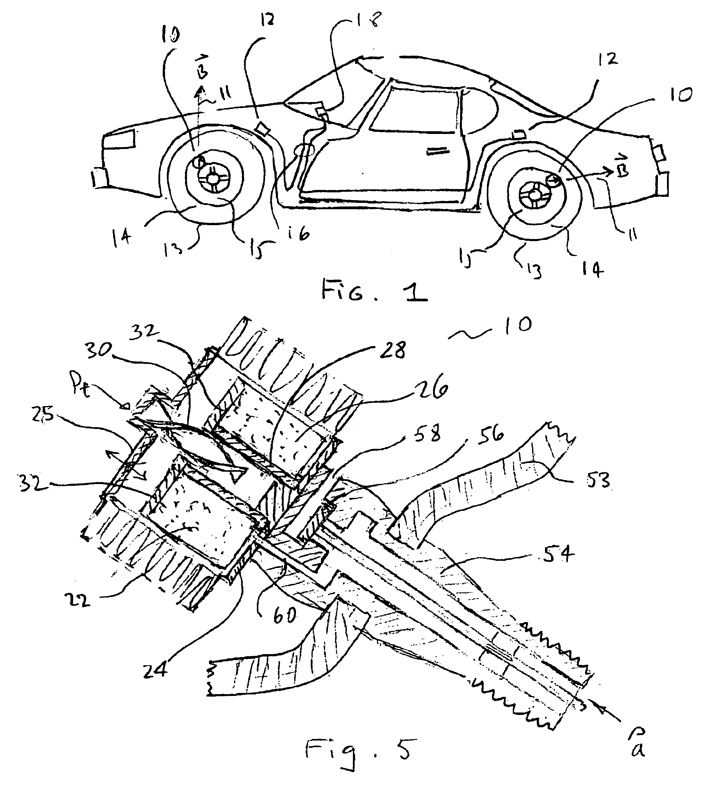
FIG. 4A is an elevation view of a vehicle wheel 13 comprising tire 14 and rim 15.

FIG. 4B is a cross section view through tire 14, rim 15, and vehicle body member 52. Tire 14 and rim 15 form a pressure vessel 50. Within vessel 50 magnetically coupled pressure sender 10 is attached to valve stem 54. Alternatively, sender 10 may be part of valve stem 54. In response to the pressure within vessel 50 sender 10 produces a magnetic field 11 oriented at a characteristic “pressure angle”θ with respect to radius Rs of sender 10 from axle 51 of wheel 15. Magnetically coupled pressure reader 12 is located at radius Rr from the axle of wheel 15. Sender 10 need not be in the same plane perpendicular to axle 51 of wheel 13 as the plane with reader perpendicular to axle 51 of wheel 13. Furthermore, the orientation of axis of sender 10 may be arbitrary with respect to axle 51.

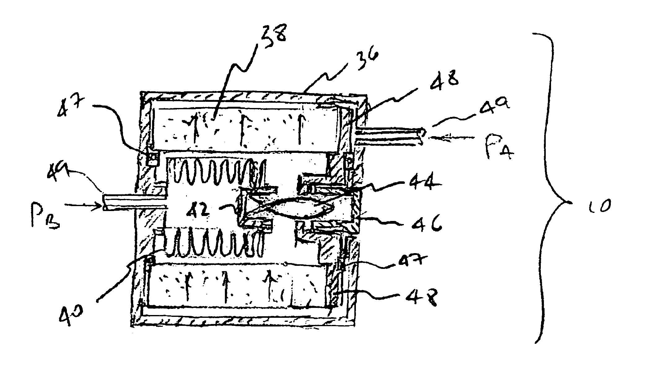
FIG. 5 shows a cross section of a magnetic pressure sender 10 combined with valve stem 54. Valve s...


PUM


Abstract

A tire pressure reporting and warning system employs low-cost passive magnetically coupled pressure senders within the tires. These senders employ permanent magnets that rotate in response to pressure and may conveniently be mounted on the valve stem. A sender comprises a high-permeability helical ribbon that translates in response to pressure and penetrates a magnetic circuit. The magnetic circuit rotates into alignment with the helical ribbon. A novel feature of this invention is the dual-purpose use of the magnet both as a means for producing rotation in response to pressure and simultaneously for producing the remotely sensed external magnetic field. The direction and strength of the external field depends both on the rotation of the magnet with respect to the tire and on the overall orbital motion as the tire rotates. Remote pressure readers at each wheel respond to the magnetic field components and interpret the response asymmetry in terms of tire pressure by continuously calculating response skew as the tires rotate. Analyzing skew obviates the need for tire rotation sensing and timing and eliminates magnetic strength effects. No special alignment is required between senders and readers, so the readers may be mounted rather arbitrarily nearby the vehicle wheels.

Description

STATEMENT REGARDING FEDERALLY SPONSORED RESEARCH AND DEVELOPMENTNot applicable.BACKGROUND1. Field of InventionThis invention relates specifically to vehicle tire pressure sensing and in general to remote pressure sensing.2. Description of Prior ArtThe U.S. Government has passed a law, known as the TREAD Act, requiring in-dash tire pressure reporting or warning systems for all new vehicles. U.S. Pat. No. 6,662,642 to Breed, et al, provides a good summary of the present art. Two main types of systems have emerged to meet this requirement—indirect and direct pressure sensing systems. The first, or indirect, type measures differential tire rotation speed to detect an anomalous rate for one tire, indirectly indicating under- or over-inflation. The advantage is passive operation with no in-tire components but the disadvantage is the inability to detect anomalous pressure in all tires. The second, or direct, type typically involves placing battery-operated transmitters within tires (possib...

Claims


Application Information

Patent Timeline
IPC IPC(8): B60C23/04B60C23/02
CPCB60C23/0425
Inventor BURNS, ALAN ALEXANDER
Owner BURNS ALAN ALEXANDER
Why Eureka
Try Eureka