Tape winder

Inactive Publication Date: 2005-02-15
FUJIFILM CORP +1
View PDF6 Cites 3 Cited by
  • Summary
  • Abstract
  • Description
  • Claims
  • Application Information

AI Technical Summary

Benefits of technology

The tape position control device may comprise a crown roller. The use of the crown roller can stabilize the traveling of the tape and does not allow the tape to fluctuate in the width direction.
Preferably, the tape winder further comprises a control device for the nozzle which keeps a constant distance between the nozzle and the outer peripheral surface of the tape roll. Hence, a constant wind pressure is always applied to the outer peripheral surface of the tape roll by the nozzle and, therefore, the tape can be wound with an adequate winding tightness.
In order to attain the above-described object, the present invention is also directed to a tape winder, comprising: a winding shaft which winds a tape to form a tape roll; a nozzle which blows a gas toward an outer peripheral surface of the tape roll at a winding time of the tape; a moving device which moves the nozzle in forward and backward directions with respect to the winding shaft; a distance sensor which measures a distance between the nozzle and the outer peripheral surface of the tape roll; and a control device which controls the moving device according to measurement values outpu

Problems solved by technology

In this winder, when the wind pressure applied to the tape roll fluctuates, there occur various troubles.
For example, when the wind pressure decreases, the air caught between the tape winds increases and there occur troubles in that the tape winding becomes loose and the edges of the wound tape are not aligned.
On the contrary, when the wind pressure increases, the winding tightness increases, and an adverse effect is inflicted upon the quality to cause the increase of the winding tightness, a damage on the tape and the like.
However, the method of making a numerical operation of a winding diameter requires an operation of the winding diameter including an eccentricity quantity of the tape roll at a high speed and, therefore, there is a problem in that not only an expensive high speed operational equipment, but also a complex control system for correcting a nozzle position at a high speed according to calculation results is required.
Further, in the case where a fluctuation of a tape thickness is high, the nozzle sometimes

Method used


Image

  • Tape winder
  • Tape winder
  • Tape winder

Examples


first embodiment

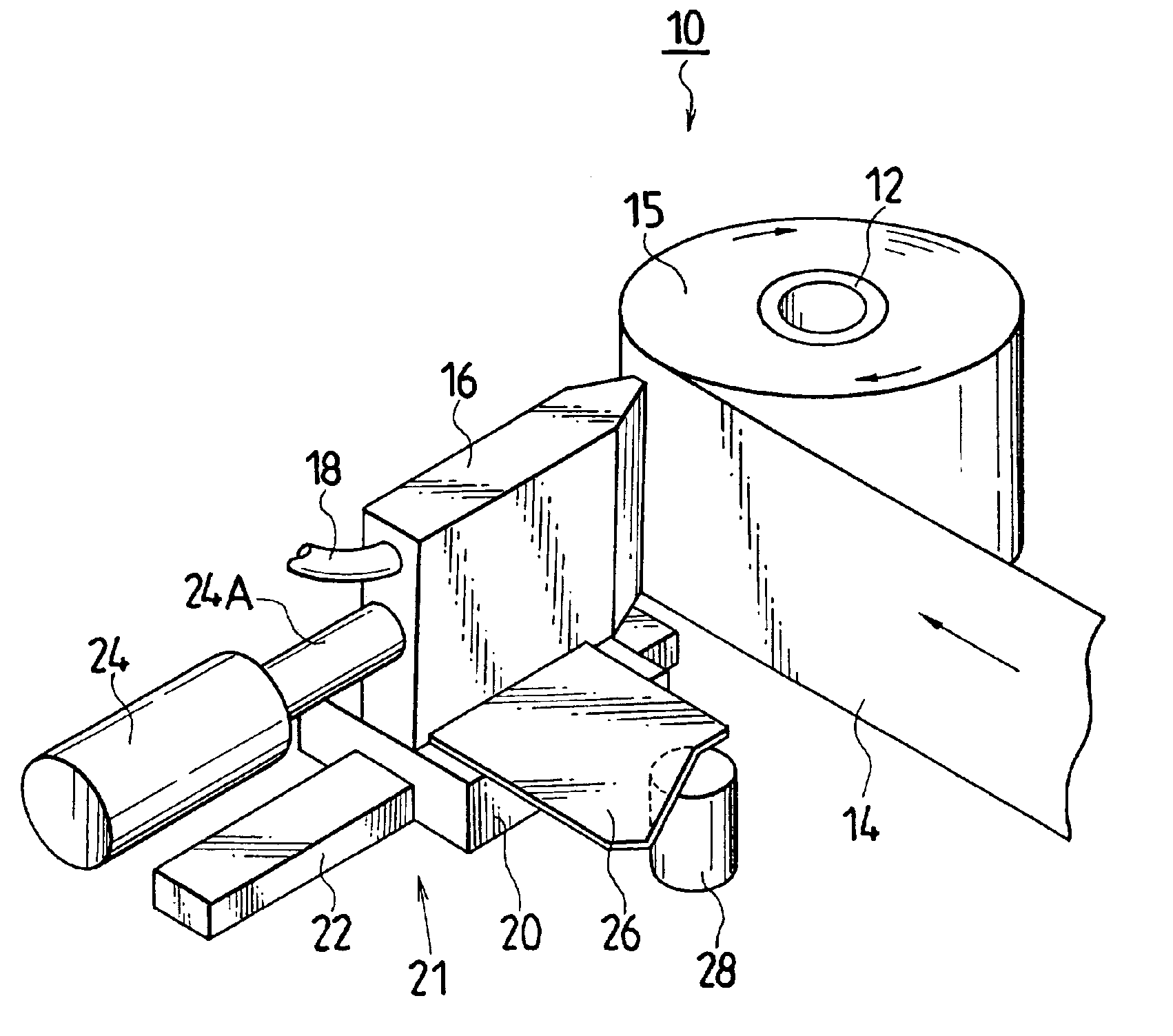
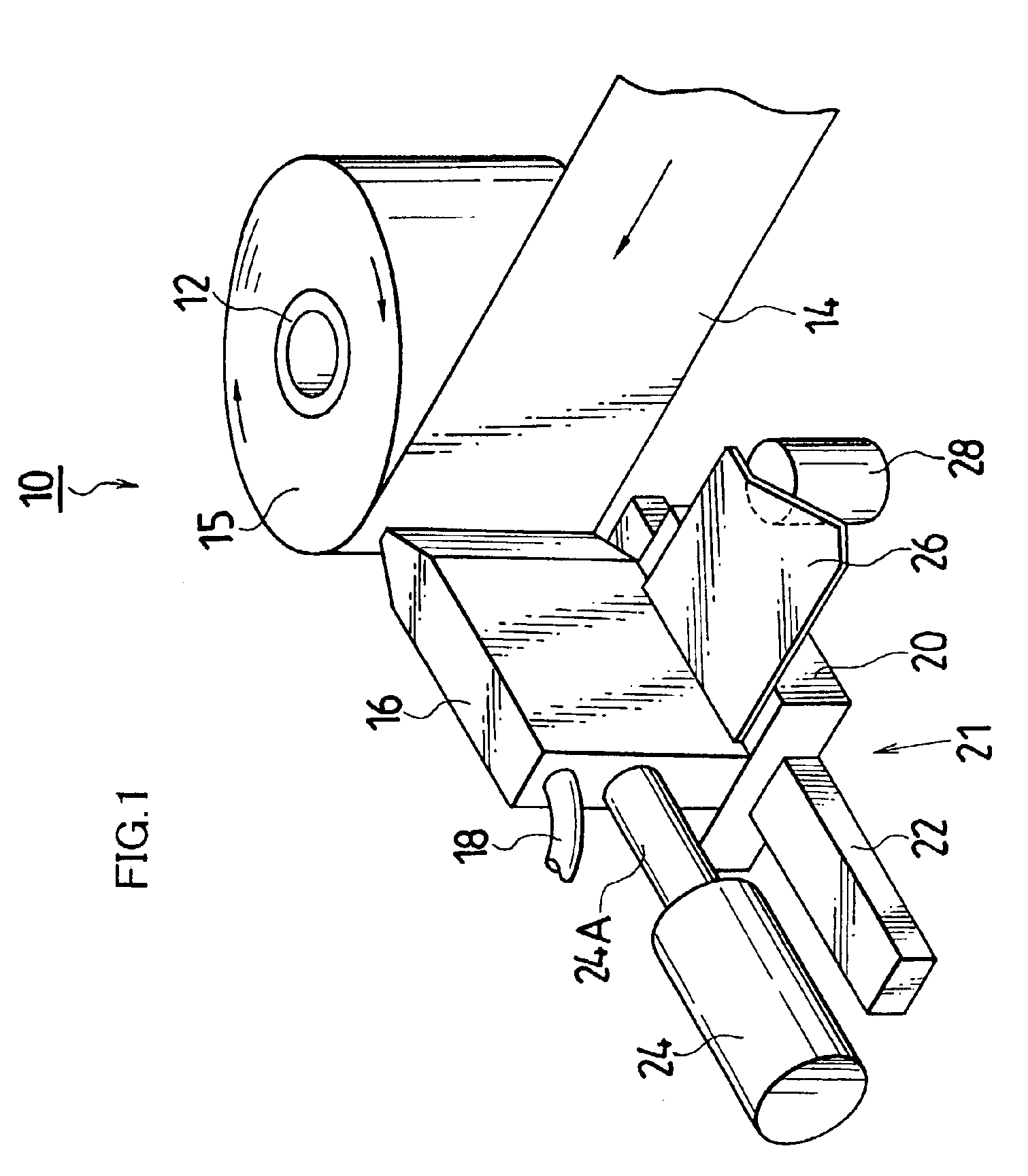
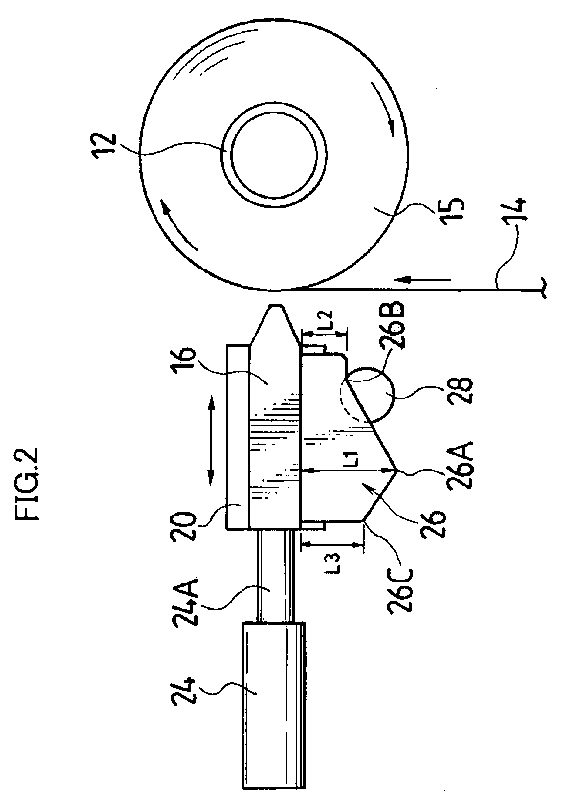
FIG. 1 is a perspective view showing the tape winder according to the present invention, and FIG. 2 is a top view thereof.

As shown in FIGS. 1 and 2, a winder 10 of the first embodiment has a reel (equivalent to a winding shaft) 12, and this reel 12 is rotated by the driving of a motor (not shown). In this way, a tape 14 is wound on the outer peripheral surface of the reel 12, thereby forming a tape roll 15.

A nozzle 16 is arranged in such a manner as to be opposed to the outer peripheral surface of the tape roll 15, and is connected to an air supply source (not shown) through a hose 18. The top end of the nozzle 16 is formed with a long and slit shaped opening (not shown) in the width direction of the tape 14, and a gas such as a compressed air and the like is blown out from this opening at a flow rate of, for example, 5 to 50 (NL / mm2·min) toward the outer peripheral surface of the tape roll 15. The opening of the nozzle 16 is formed almost in the same width as that of the tape 14 (t...

second embodiment

Next, the winder according to the present invention will be described.

FIG. 8 is a perspective view showing a winder 100 of a second embodiment and FIG. 9 is a top view of the same. Note that, in these drawings, the components having almost the same functions, constitutions as those of the winder 10 of the first embodiment will be designated by the same reference numerals and the description thereof will be omitted.

An opening formed at the top end of a nozzle 16 is formed almost by the same width as that of a tape 14 (that is, a tape roll 15), and it is important that, by the air blown out from the opening, an outer peripheral surface of the tape roll 15 is pressed uniformly in a width direction. However, the opening of a nozzle 16 is not limited to almost the same width as the tape width.

The rear of the nozzle 16 is provided with an air cylinder 24 and, by the top end of a rod 24A of the air cylinder 24, the nozzle 16 is pressed toward the tape roll 15 side by a constant pressing fo...


PUM


Abstract

In the tape winder for winding a tape on a reel to form a tape roll, a nozzle which blows a gas toward an outer peripheral surface of the tape roll at a winding time of the tape is fixed on a slider, which is slidably supported on a rail. In this way, the nozzle is supported movably forward and backward with respect to the tape roll. Moreover, the nozzle is pressed toward the tape roll by an air cylinder with a constant pressing force. Thus, the nozzle is allowed to accurately follow an outer peripheral surface of the tape roll, and a constant pressure can be applied to the outer peripheral surface of the tape roll. Consequently, the tape can be wound with an adequate winding tightness.

Description

BACKGROUND OF THE INVENTION1. Field of the InventionThe present invention relates to a tape winder and, more in particular, to a winder for winding a long and narrow piece of matter such as a magnetic tape and the like on a winding shaft in a roll shape.2. Description of the Related ArtJapanese Patent Application Publication No. 6-329308 discloses a tape winder, which comprises a pressure roll rotationally contacting the outer peripheral surface of a tape roll at a winding time, a wind pressure device which blows an air to the outer peripheral surface of the tape roll at the winding time, and a movable portion moving device which displaces the pressure roll and the wind pressure device according to a winding diameter of the tape roll. In this winder, when the wind pressure applied to the tape roll fluctuates, there occur various troubles. For example, when the wind pressure decreases, the air caught between the tape winds increases and there occur troubles in that the tape winding b...

Claims


Application Information

Patent Timeline
IPC IPC(8): B65H18/08B65H18/26
CPCB65H18/26Y10S242/908B65H2601/211B65H2406/00B65H18/08
Inventor HAYASHI, YOICHIKITA, AKIHISAUCHIUMI, KYOHISA
Owner FUJIFILM CORP
Why Eureka
Try Eureka