Optical receptacle, transceiver and cage

a technology of optical receptacles and transceivers, applied in the field of optical receptacles transceiver housings, transceiver cages and transceiver mountings, can solve the problems that existing lc small form factor (sff) or small form factor pluggable transceivers are not able to be mounted on a standard pwa to provide additional ports

Inactive Publication Date: 2005-02-15
JDS UNIPHASE CORP
View PDF14 Cites 210 Cited by
  • Summary
  • Abstract
  • Description
  • Claims
  • Application Information

AI Technical Summary

Benefits of technology

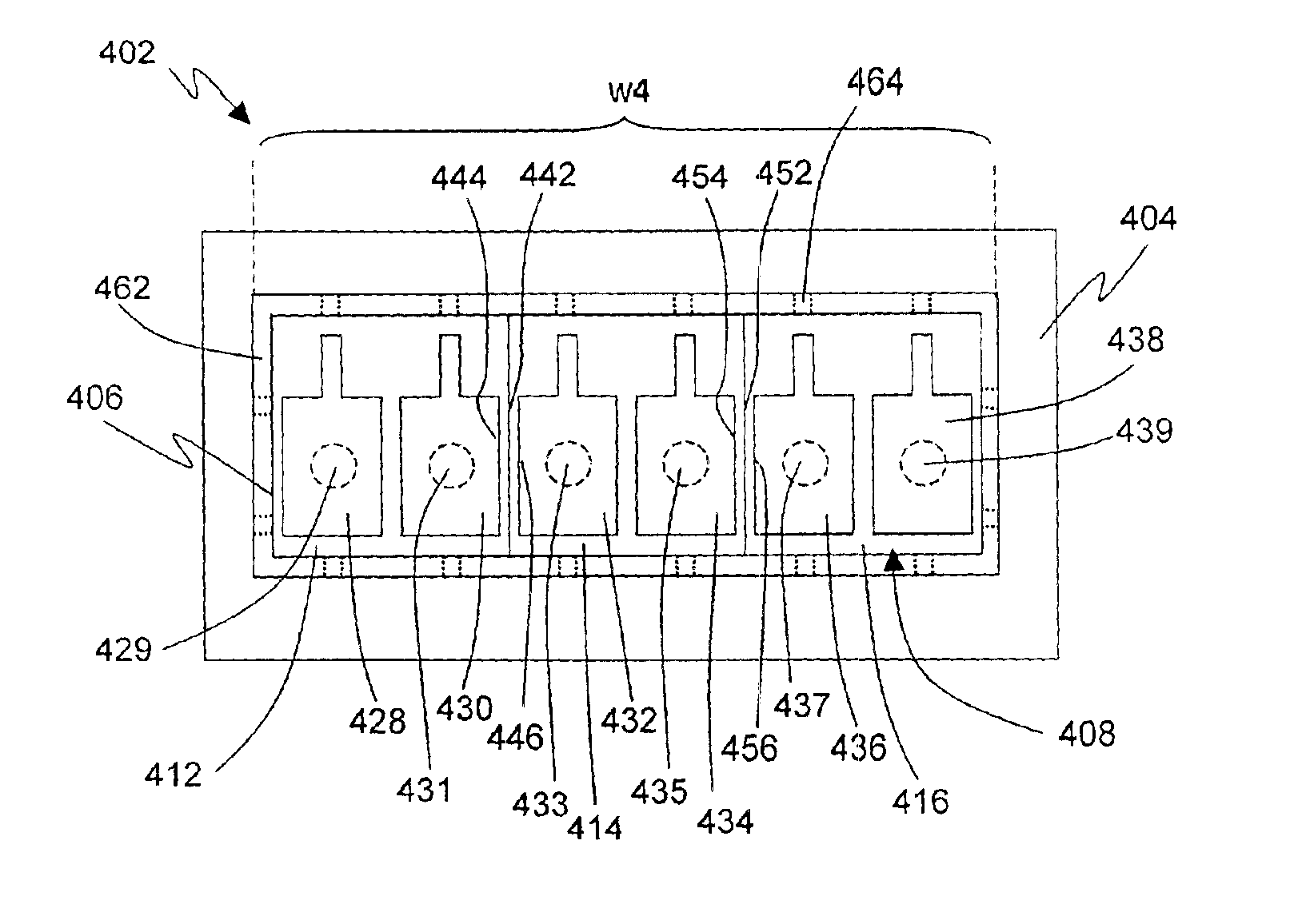
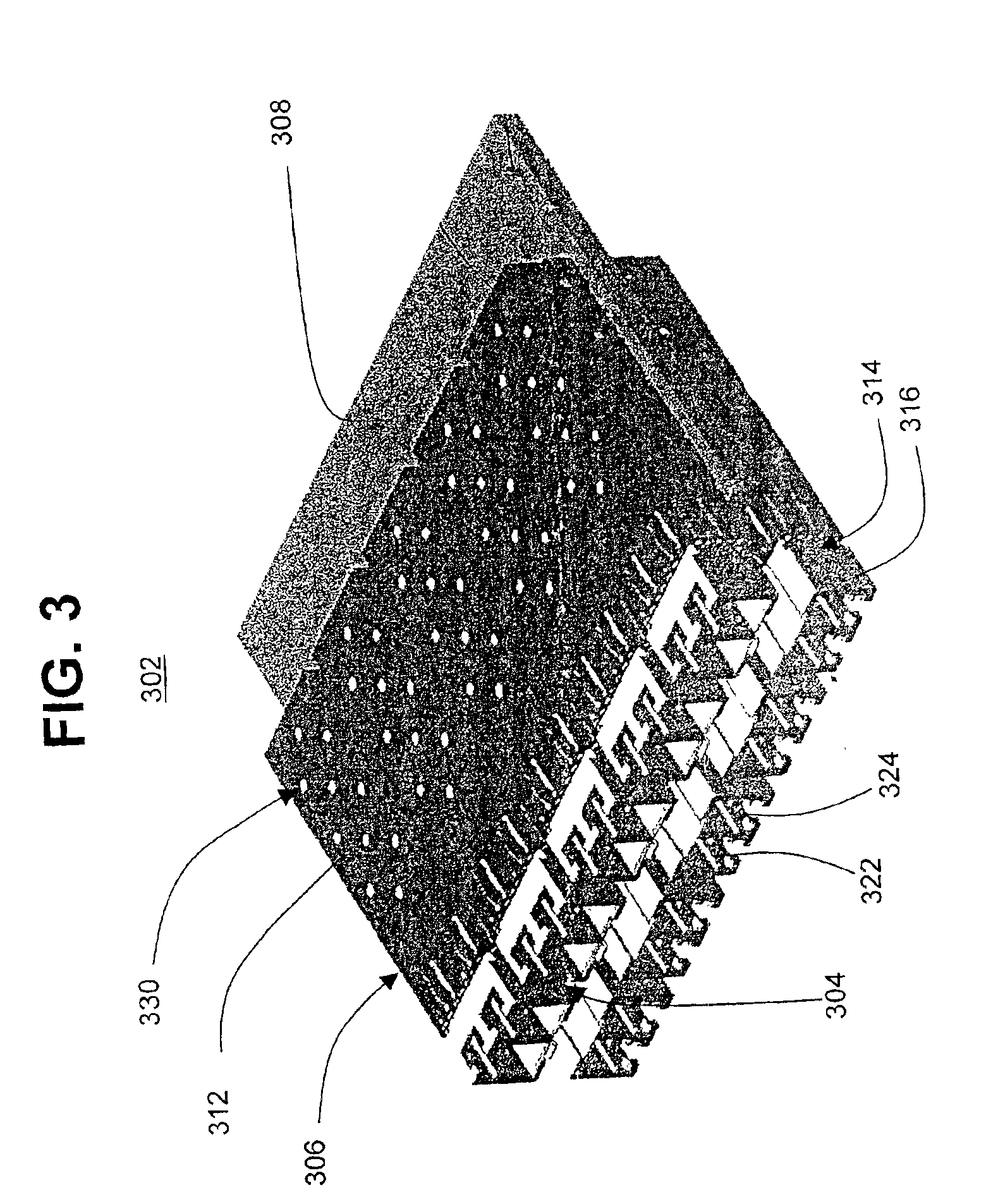
According to a third broad aspect of the present invention there is provided a multi-transceiver cage comprising a hollow cage body for mounting at least two transceivers within said multi-transceiver cage and for preventing electromagnetic radiation from outside said cage body from entering said cage body and for preventing radiation from said transceiver from exiting said cage body; a plurality of mounting pins extending from said cage body for mounting said transceiver on a printed wiring board; and a plurality of internal contact fingers at a proximal open end of said hollow cage body for engaging a chassis panel through which said transceiver cage is inserted and for engaging said at least two transceivers.
According to a fourth broad aspect of the present invention there is provided an optoelectronic device comprising at least two transceivers; and a transceiver cage comprising a hollow cage body for mounting said least two transceivers within said multi-transceiver cage and for preventing radiation from outside said cage body from entering said cage body and for preventing radiation from said transceiver from exiting said cage body; a plurality of mounting pins extending from said cage body for mounting said transceiver on a printed wiring board; and a plurality of internal contact fingers at a proximal open end of said hollow cage body for engaging a chassis panel through which said transceiver cage is inserted and for engaging said at least two transceivers.
According to a seventh broad aspect of the present invention there is provided an optoelectronic device assembly comprising a PWA; and at least one optoelectronic device mounted on at least one side of said PWA, wherein said at least one optoelectronic device comprises at least two transceivers; and a transceiver cage comprising a hollow cage body for mounting said least two transceivers within said multi-transceiver cage and for preventing radiation from outside said cage body from entering said cage body and for preventing radiation from said transceiver from exiting said cage body; a plurality of mounting pins extending from said cage body for mounting said transceiver on a printed wiring board; and a plurality of internal contact fingers at a proximal open end of said hollow cage body for engaging a chassis panel through which said transceiver cage is inserted and for engaging said at least two transceivers.

Problems solved by technology

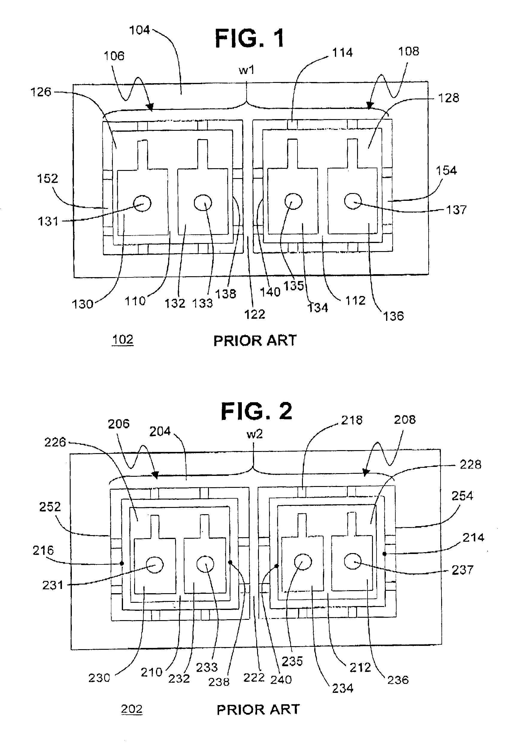
However, existing LC Small Form Factor (SFF) or Small Form Factor Pluggable (SFP) transceivers are not able to be mounted on a standard PWA to provide additional ports without turning the PWA vertically to gain length.

Method used


Image

  • Optical receptacle, transceiver and cage
  • Optical receptacle, transceiver and cage
  • Optical receptacle, transceiver and cage

Examples


Embodiment Construction

It is advantageous to define several terms before describing the invention. It should be appreciated that the following definitions are used throughout this application.

Definitions

Where the definition of terms departs from the commonly used meaning of the term, applicant intends to utilize the definitions provided below, unless specifically indicated.

For the purposes of the present invention, the term “port” refers to an electrical or optical interface that may be used in a transmitter or receiver for transmitting or receiving information.

For the purposes of the present invention, the term “transceiver” refers to an electrical or optical transmitter, an electrical or optical receiver, or an electrical or optical transceiver. Unless otherwise specified, a “transceiver” refers to an optical transceiver comprising two ports, one port comprising a transmit port and one port comprising a receive port.

For the purposes of the present invention, the term “proximal” refers to the end of a tr...


PUM


Abstract

The present invention provides multi-optoelectronic assemblies in which a plurality of multi-receiver cages in which are mounted multi-optical receptacle assemblies associated with a plurality of transceivers are mounted on a printed wire assembly. The multi-optical receptacle assemblies includes a plurality of receptacles having shared walls, unitary walls or no walls. The multi-optoelectronic assemblies are compatible with multi-fiber assemblies.

Description

BACKGROUND OF THE INVENTION1. Field of the InventionThe present invention relates generally to optical receptacles transceiver housings, transceiver cages and transceiver mountings.2. Description of the Prior ArtExisting optical transceivers may be mounted on a standard printed wire assembly (PWA) to provide a maximum of 20 ports in the width of standard 19-inch equipment. If double-sided mounting of the transceiver is done on a PWA then the number of ports may be increased to 40. There has been a need to increase the port density on a standard PWA further in order to keep up with increasing system bandwidth and interconnection density needs. However, existing LC Small Form Factor (SFF) or Small Form Factor Pluggable (SFP) transceivers are not able to be mounted on a standard PWA to provide additional ports without turning the PWA vertically to gain length.Thus there is a need for a way to increase the linear port density to more than 20 ports on one side and more than 40 ports on t...

Claims


Application Information

Patent Timeline
Patent Type & Authority Patents(United States)
IPC IPC(8): G02B6/42G02B6/43G02B6/44
CPCG02B6/43G02B6/4453G02B6/4255G02B6/4261G02B6/4245G02B6/4277
Inventor YUNKER, BRYANKAYNER, ANDREW
Owner JDS UNIPHASE CORP
Why Eureka
Try Eureka