
Seal of a vertical pump

a vertical pump and sealing technology, applied in the direction of piston pumps, positive displacement liquid engines, liquid fuel engines, etc., can solve the problems of ineffective v-type oil sealing, increased defect rate of air bubbles during the manufacturing process of printed circuit boards, and ineffective sealing, so as to eliminate air bubbles

Inactive Publication Date: 2005-02-15
ASSOMA
View PDF6 Cites 8 Cited by
  • Summary
  • Abstract
  • Description
  • Claims
  • Application Information

AI Technical Summary

Benefits of technology

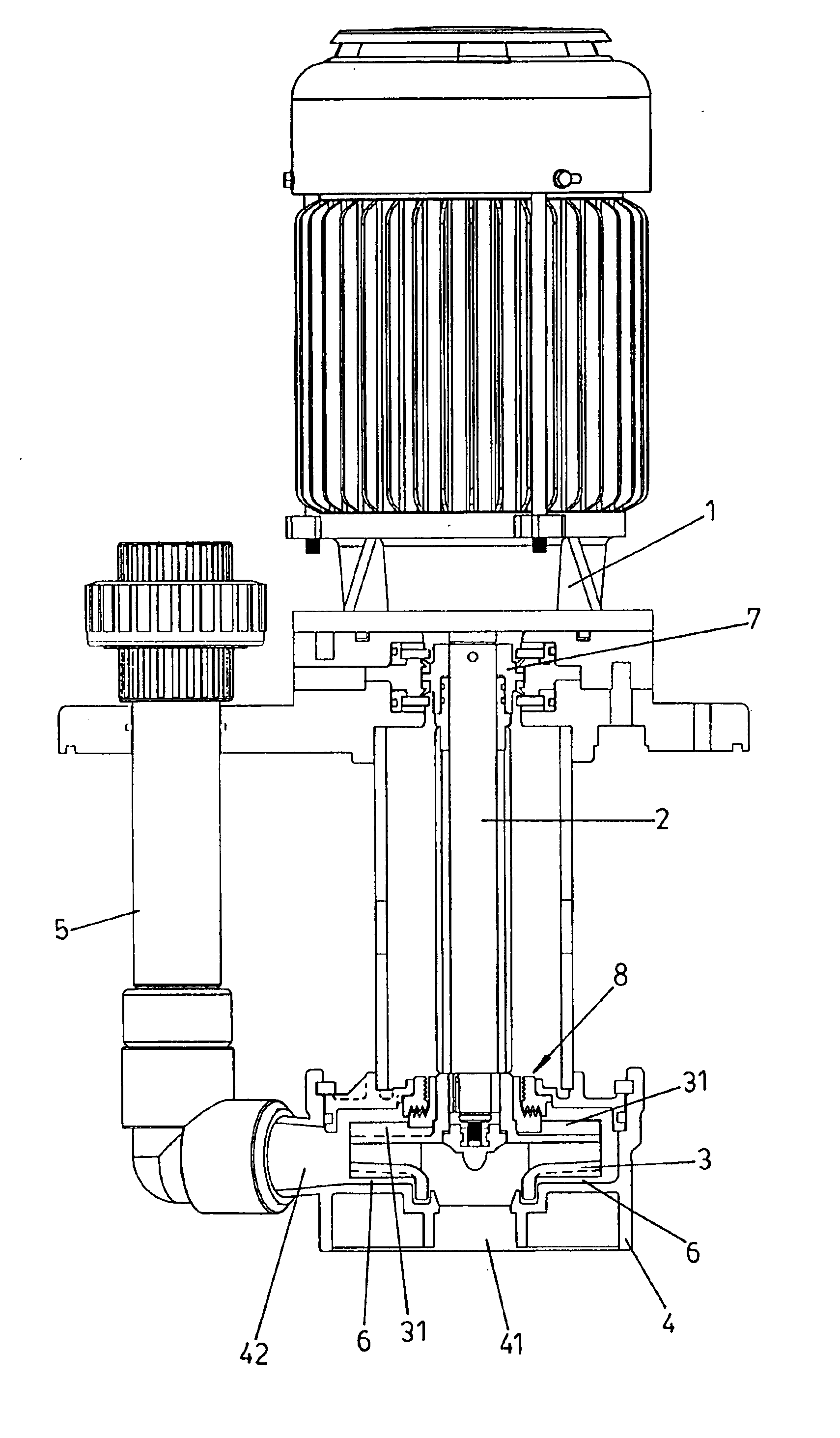
Therefore, the primary objective of the present invention is to dispose a non-contact seal on the impeller of a vertical pump to prevent a back vane from stirring the air and causing the pump to eject a liquid with a lot of bubbles so as to eliminate the air bubbles from causing any serious undesired effect during the manufacturing process of a printed circuit board.
Another objective of the present invention is to dispose the non-contact seal as a non-contact labyrinth seal so as to prevent the liquid crystallization which might jam the seal, and to eliminate the heat generation due to the friction of the seal.

Problems solved by technology

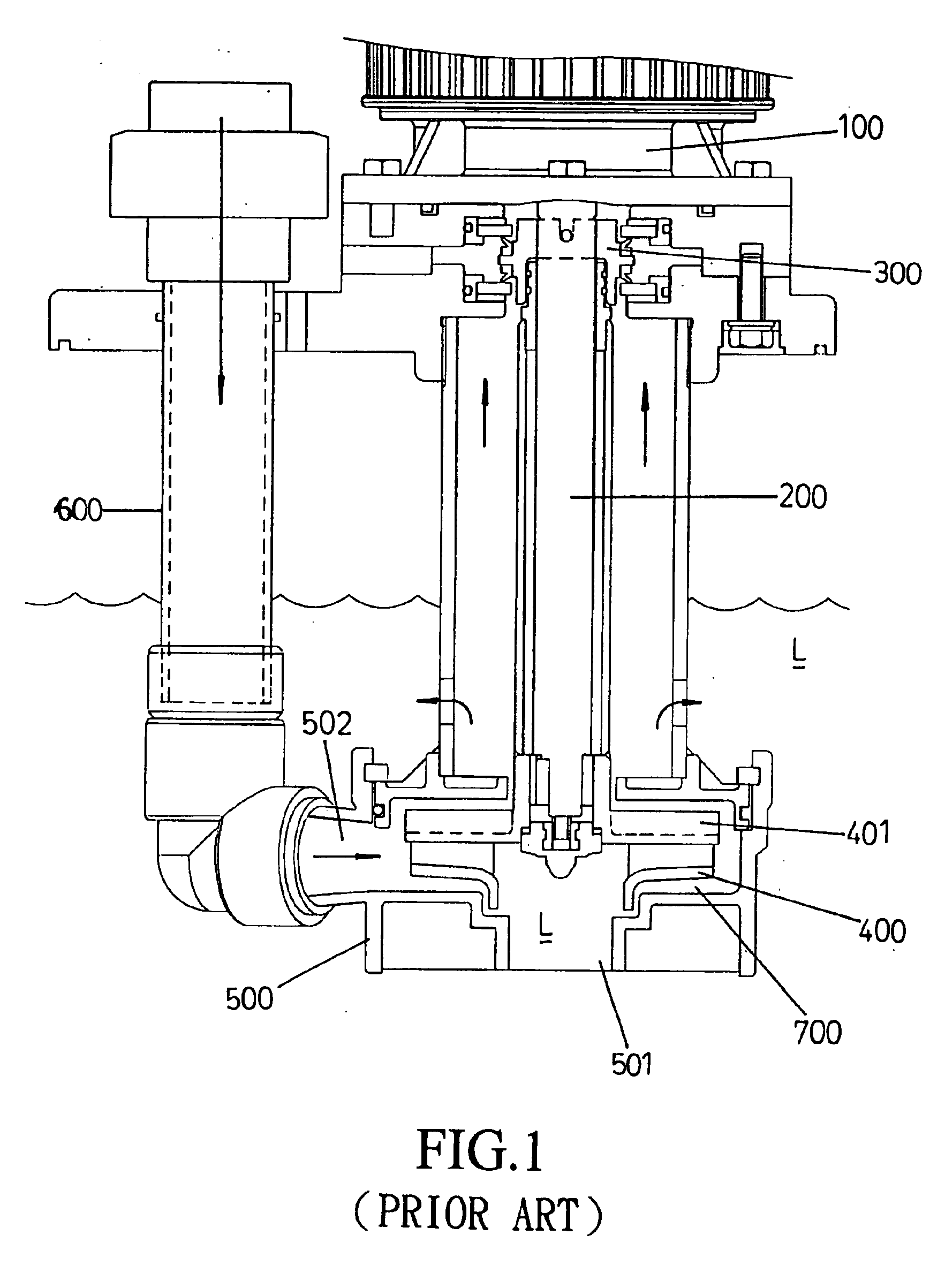
The main purpose of the seal device is to block the acid and alkali liquid because the V-type oil seal (300) becomes ineffective once it contacts the liquid, especially liquid that crystallizes.
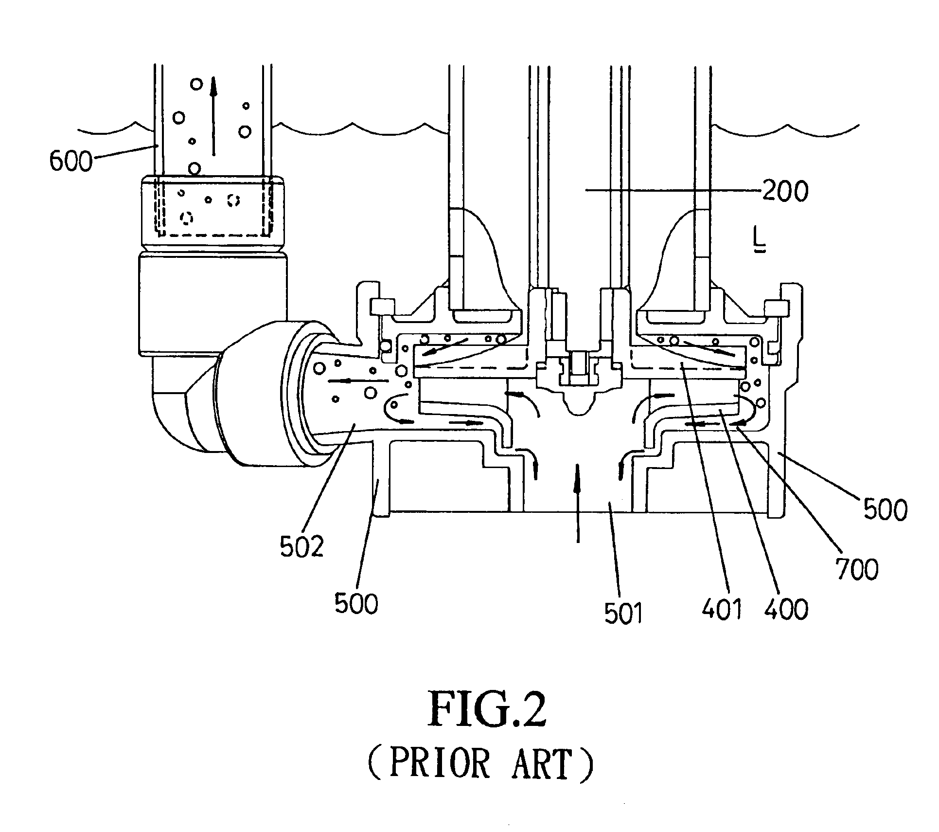
1. It uses the back vane (401) to eliminate the back pressure of the impeller (400). However, the back vane (401) stirs the air and the delivery liquid to create a lot of air bubbles; the air bubbles tremendously increase the defect rate during the manufacturing process of a printed circuit board.
2. When the pump stops and the back vane (401) is not working, the liquid flows toward the V-type seal (300) above the liquid surface in a similar water hammer effect. If the liquid left on the seal device crystallizes, it damages the V-type seal (300) device or the lip seal. Although some manufacturers suggested the use of a check valve to solve this problem, most of the machines do not have enough space for installation, and the crystallization might make the check valve inefficient.

Method used


Image

  • Seal of a vertical pump
  • Seal of a vertical pump
  • Seal of a vertical pump

Examples


Embodiment Construction

As indicated in FIGS. 3 and 4, the present invention of a vertical pump comprises a front casing (4) disposed on a main casing which has a motor (1) disposed therein; a cantilever shaft (2) of the motor (1) is located toward the front casing (1); a volute chamber (6) is disposed inside the front casing (4) for placing a centrifugal impeller (3); a suction inlet (41) is disposed axially on the front casing (4) opposite the motor (1); a water outlet (42) is disposed on the casing opposite the lateral side of the impeller (3) to engage with a discharge pipe (5); both the suction inlet (41) and the water outlet (42) are in communication with the volute chamber (6). The V-type oil seal (7) device is axially mounted on the cantilever shaft (2) near the motor (1).

The present invention is mainly characterized by a non-contact seal (8) that is disposed on the impeller (3). The functions of the non-contact seal (8) of the present invention are as follows:

1. It prevents a back impeller vane fr...


PUM


Abstract

A seal of a vertical pump with a front casing disposed on a main casing which has a motor disposed therein. A volute chamber is disposed inside the front casing to receive a centrifugal impeller. A suction inlet is disposed axially on the front casing opposite the motor. A water outlet is disposed thereon opposite the lateral side of the impeller to engage with a discharge pipe. The suction inlet and outlet are in communication with a volute chamber. The pump has a non-contact seal disposed on the impeller. The seal can jam when a liquid crystallizes. Therefore, if no heat is generated due to the friction of the seal, the pump operates better. Furthermore, it prevents a back impeller vane from stirring the air and ejecting the liquid with a lot of air bubbles when the pump operates. Therefore, it eliminates the air bubbles from causing problems during the manufacturing process of a printed circuit board.

Description

BACKGROUND OF THE INVENTION1) Field of the InventionThe present invention relates to a seal of a vertical pump, and more particularly to a structure having a non-contact and improved labyrinth seal disposed on the impeller.2) Description of the Prior ArtAs indicated in FIGS. 1 and 2, a traditional pump is used at a chemical engineering site for pumping and delivering strong acid, alkali, and corrosive liquid. A cantilever shaft (200) disposed at the front end of a motor (100); a V-type oil seal (300) or a lip seal is disposed near the tail end of the cantilever shaft (200). The main purpose of the seal device is to block the acid and alkali liquid because the V-type oil seal (300) becomes ineffective once it contacts the liquid, especially liquid that crystallizes. That would further corrode an axle center of the motor (100). The front end of the cantilever shaft (200) vertically connects with an axle center of an impeller (400); the backside of the impeller (400) is disposed with a...

Claims


Application Information

Patent Timeline
IPC IPC(8): F04D29/08F04D29/10
CPCF04D29/106
Inventor SHI, CHI WEI
Owner ASSOMA
Learn More