
Implant and agent delivery device

Inactive Publication Date: 2005-02-15
CR BARD INC
View PDF198 Cites 22 Cited by
  • Summary
  • Abstract
  • Description
  • Claims
  • Application Information

AI Technical Summary

Benefits of technology

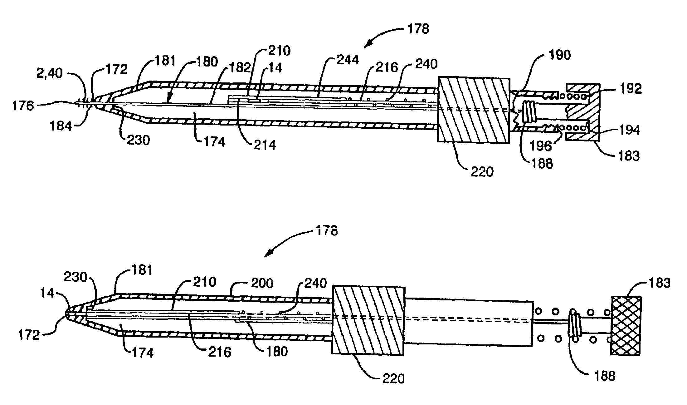
The present invention provides a system for delivering a therapeutic agent in combination with an implantable device to maximize a therapeutic benefit offered by each. Preferably, the therapeutic agent is contained within a solid matrix form such as a pellet or gel to facilitate its handling and to regulate its rate of dissipation into the tissue after delivery. The implant device is specially configured to receive and retain the pellet but permit blood to interact with the pellet so that the agent can be released to the blood in and around the device and the surrounding tissue. A delivery system comprises an implant delivery device having an obturator capable of piercing the tissue and an agent matrix delivery device to place a matrix form, such as a pellet, into the interior of the implant after it has been implanted. Preferably, the implant delivery device and the pellet delivery device are contained in one apparatus to facilitate delivery of the pellet into the embedded implant.
It is another object of the invention to provide a delivery method for sequentially delivering the implant device and a matrix containing a therapeutic substance that is. relatively simple and effective.

Problems solved by technology

Furthermore, the presence of a device in the moving tissue of a muscle such as the myocardium, creates an irritation or injury to the surrounding tissue which further promotes an injury response and the coagulation cascade that leads to new vessel growth.
Additionally the implant causes a foreign body response, which causes inflammation attracting macrophages, which cause secretion of growth factors.

Method used


Image

  • Implant and agent delivery device
  • Implant and agent delivery device
  • Implant and agent delivery device

Examples


Embodiment Construction

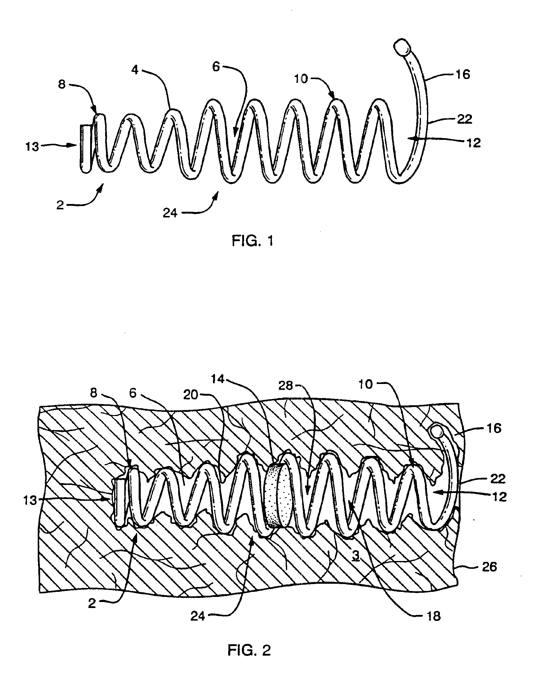
FIG. 1 shows a side view of an implant device 2 of the present invention. In a preferred embodiment the implant device 2 comprises a flexible helical coil having a plurality of individual coils 4 that define an interior 6. The device preferably has a distal region 8 and proximal region 10. The coils at the distal region 8 define a diameter that is smaller than that defined by the coils of proximal region 10. However, an agent carrying matrix, such as a pellet, may be inserted through proximal opening 12 into the proximal region 10 of the implant. The coils 4 of the distal region 8 are sized smaller than the pellet so that the pellet cannot slip out of the implant through the distal region. In the present application, proximal is understood to mean the direction leading external to the patient and distal is understood to mean a direction leading internally to the patient.

It should be noted that the agent carrying matrix may, but need not be a pellet form. A pellet may comprise a pill...


PUM


Abstract

The present invention provides a system for delivering a therapeutic agent in combination with an implanted device to maximize a therapeutic benefit offered by each. Preferably, the therapeutic agent is contained within a solid matrix form such as a pellet or gel to facilitate its handling, and to regulate its rate of dissipation into the tissue after delivery. The implant device is specially configured to receive retain the matrix but permit blood to interact with the matrix so that the agent can be released to the blood in, around the device, and the surrounding tissue. A delivery system comprises an implant delivery device having an obturator capable of piercing the tissue and an agent matrix delivery device to place a matrix form, such as a pellet, into the interior of the implant after it has been implanted. Preferably, the implant delivery device and the matrix delivery device are contained in one apparatus to facilitate delivery of the pellet into the embedded implant. The present invention is useful for treating tissue in any area of the body, especially ischemic tissue experiencing reduced blood flow. The present devices and methods are especially useful for treatment of ischemia of the myocardium. In treatment of the myocardium, the present implant device and matrix combination may be delivered surgically through the epicardium of the heart.

Description

FIELD OF THE INVENTIONThe present invention relates to delivery of a therapeutic agent to tissue in combination with an implant device. Specifically, the agent is contained in a matrix form capturable within the implant device to provide the therapeutic advantages provided by both in a single treatment.BACKGROUND OF THE INVENTIONTissue becomes is ischemic it is deprived of adequate blood flow. Ischemia causes pain in the area of the affected tissue and, in the case of muscle tissue, can interrupt muscular function. Left untreated, ischemic tissue can become infarcted and permanently non-functioning. Ischemia can be caused by a blockage in the vascular system that prohibits oxygenated blood from reaching the affected tissue area. However, ischemic tissue can be revived to function normally despite the deprivation of oxygenated blood because ischemic tissue can remain in a hibernating state, preserving its viability for some time. Restoring blood flow to the ischemic region serves to ...

Claims


Application Information

Patent Timeline
IPC IPC(8): A61F2/06A61F2/00A61F2/02A61F2/88
CPCA61F2/06A61F2/2493A61F2/88A61F2220/0016A61F2250/0067
Inventor GAMBALE, RICHARD A.FORCUCCI, STEPHEN J.WEISER, MICHAEL F.FORDE, SEAN
Owner CR BARD INC
Learn More