Device in a leg prosthesis

a technology for leg prosthesis and device, which is applied in the field of devices in leg prosthesis, can solve the problems of difficulty in resisting knee collapsing, difficulty in walking downhill slopes, and high manufacturing cost of prosthesis types, and achieve the effect of reducing manufacturing cost and simple geometries

Inactive Publication Date: 2005-02-15
GRAMTEC INNOVATION
View PDF21 Cites 157 Cited by
  • Summary
  • Abstract
  • Description
  • Claims
  • Application Information

AI Technical Summary

Benefits of technology

An object of the invention is to provide a device in a leg prosthesis provided with a foot which via a pivot axle is connected to the leg prosthesis and wherein the angular position between the foot and the leg prosthesis is adjustable to a desired angular position and which admits a compact installation of ...

Problems solved by technology

It is well-known among prosthesis wearers that walking in downhill slopes is problematic.
If the foot angle exceeds a certain degree it will due to the absence of certain muscle groups be difficult to resist the knee from collapsing.
Prosthesis...

Method used


Image

  • Device in a leg prosthesis
  • Device in a leg prosthesis
  • Device in a leg prosthesis

Examples


Embodiment Construction

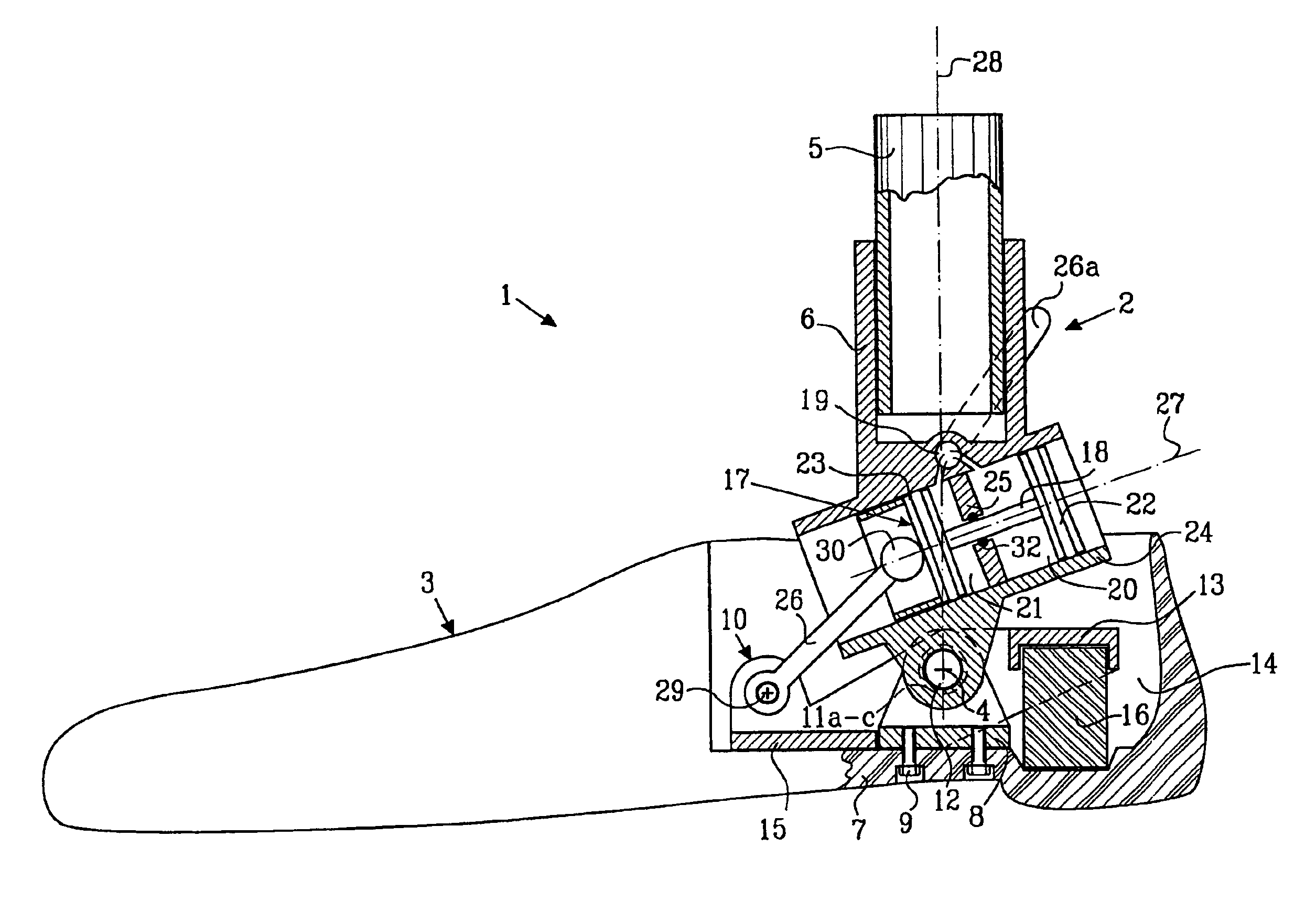
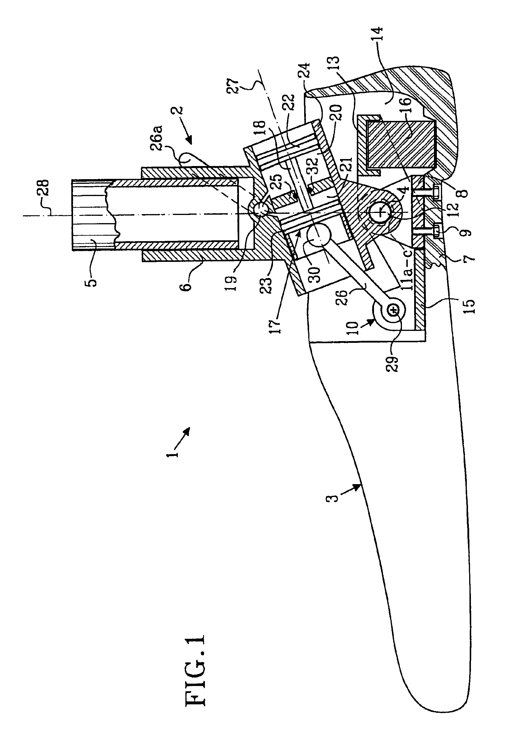
In FIG. 1 there is shown a prosthesis generally denoted 1. The prosthesis comprises a leg prosthesis 2 and a foot 3. The leg prosthesis connected to the foot via a pivot axle 4. The leg prosthesis is constructed in a manner well-known to the person skilled in the art, for example with a tubular lower leg portion 5 which is attached in a socket 6, said socket being connected to or comprising said pivot axle 4. The foot 3 is also constructed in a manner well-known to the person skilled in the art and comprises a foot blade 7, preferably provided with a foot-like casing. The foot 3 is preferably provided with an attachment plate 8 which is connected to the pivot axle 4. The attachment plate 8 is anchored to the foot in any manner well-known to the person skilled in the art, for example by a screw or rivet joint 9. The foot 3 and the leg prosthesis 2 are via the pivot axle 4 rotatably connected to each other.

The prosthesis 1 further comprises a lever arm 10 which is pivotally connected ...


PUM


Abstract

A device in a leg prosthesis which via a pivot axle is connected to the leg prosthesis, wherein first means are arranged to permit a limited rotation of the foot with respect to the leg prosthesis from an initial position, in which the leg prosthesis and the foot have a certain angle with respect to each other and second means are arranged to permit a stepless adjustment of the angle between the prosthesis and the foot in the initial position.

Description

TECHNICAL FIELDThe present invention refers to a device in a leg prosthesis according to the preamble of claim 1. The invention especially refers to a device in a leg prosthesis provided with a foot which via a pivot axle is connected to the leg prosthesis and wherein the angular position between the foot and the leg prosthesis is adjustable to a desired angular position.BACKGROUND OF THE INVENTIONIt is well-known among prosthesis wearers that walking in downhill slopes is problematic. If the prosthesis wearer does not have the possibility to adjust the foot angle only the heel will contact the ground when walking in a steep downhill. If the foot angle exceeds a certain degree it will due to the absence of certain muscle groups be difficult to resist the knee from collapsing. Therefor the prosthesis wearer often chooses to walk sideways downhill.Prosthesis wearers that do not have a height adjustable foot have problems changing to a shoe with another heel height, and to quickly choo...

Claims


Application Information

Patent Timeline
IPC IPC(8): A61F2/66A61F2/68A61F2/50A61F2/60A61F2/74
CPCA61F2/66A61F2/68A61F2002/5003A61F2002/745A61F2002/5018A61F2002/5039A61F2002/5043A61F2002/5007A61F2/74
Inventor GRAMNAS, FINN
Owner GRAMTEC INNOVATION
Why Eureka
Try Eureka