Fuel cell system

a fuel cell and system technology, applied in the direction of fuel cells, solid electrolyte fuel cells, electrical equipment, etc., can solve the problems of preventable useless power consumption for freezing prevention processing, and achieve the effect of reducing the size of the fuel cell system and more effective gas-liquid separation

Inactive Publication Date: 2005-02-15
DENSO CORP
View PDF17 Cites 15 Cited by
  • Summary
  • Abstract
  • Description
  • Claims
  • Application Information

AI Technical Summary

Benefits of technology

This can achieve the decompression between the decompression valve (27) and the pump means (16) so that the moisture existing therebetween can be decompression-boiled to be discharged to the external.
Still furthermore, according to a ninth aspect of the present invention, the gas-liquid separator is of a centrifugal type which is rotationally driven by a drive shaft (

Problems solved by technology

Moreover, since a transition of the outside air temperature is estimated and the freezing prevention processing is conducted only in a

Method used


Image

  • Fuel cell system
  • Fuel cell system
  • Fuel cell system

Examples


first embodiment

(First Embodiment)

A first embodiment of the present invention will be described hereinbelow with reference to FIGS. 1 to 4. A fuel cell system according to this first embodiment is suitably applicable to, for example, an electric vehicle (fuel cell powered vehicle) using a fuel cell as an electric power source.

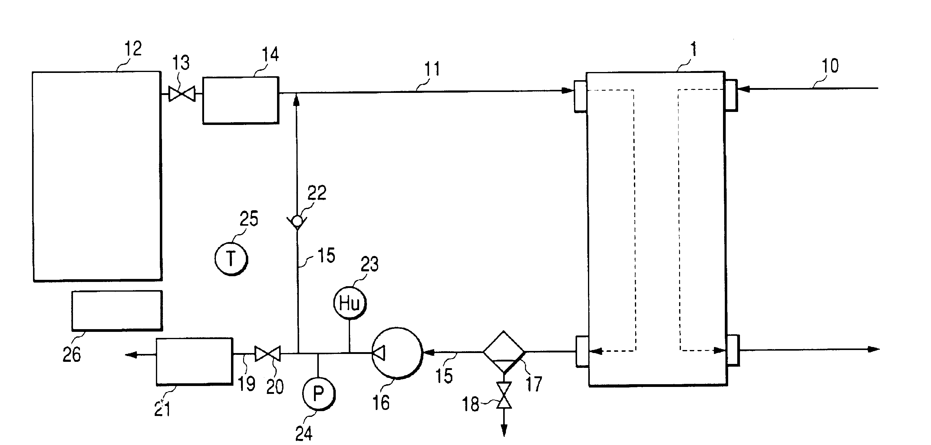
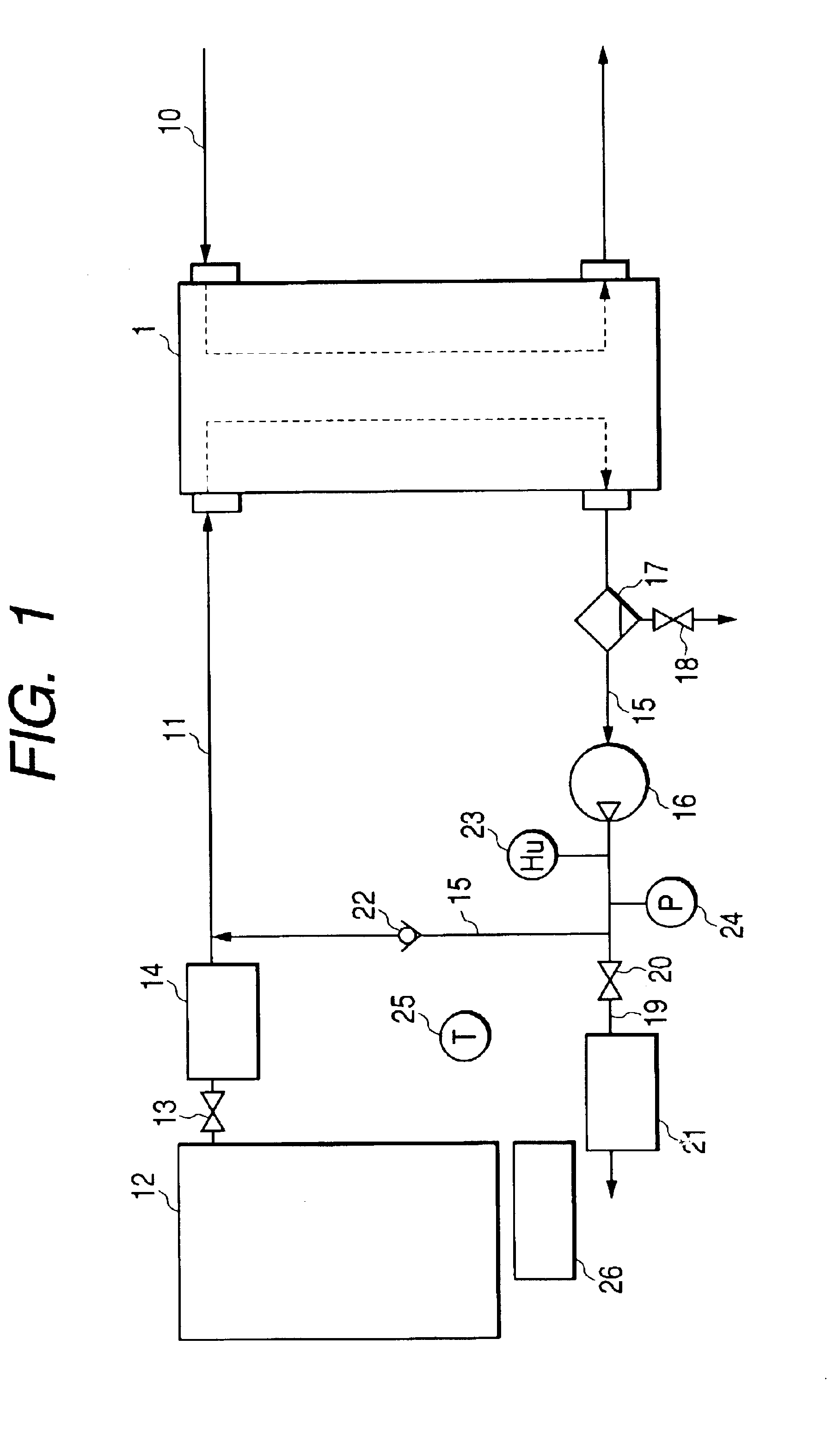
FIG. 1 is an illustration of the entire construction of a fuel cell system according to the first embodiment. A fuel cell (FC stack) 1 is designed to generate electric power through the use of electrochemical reaction between hydrogen and oxygen. In the first embodiment, a solid polyelectrolyte type fuel cell is employed as the fuel cell 1, and a plurality of cells each constitutes basic unit are formed into a laminated condition. Each of the cells is such that an electrolyte membrane is sandwiched between a pair of electrodes. The fuel cell 1 is made to supply electric power to electric equipment such as a driving motor or secondary battery (not shown). In the fuel cell 1, up...

second embodiment

(Second Embodiment)

Secondly, referring to FIG. 5, a description will be given hereinbelow of a second embodiment of the present invention. The parts corresponding to those in the above-described first embodiment are marked with the same reference numerals, and the description thereof will be omitted for brevity. The second embodiment will be described about only differences therefrom.

FIG. 5 is an illustration of the entire construction of a fuel cell system according to the second embodiment. As FIG. 5 shows, in the second embodiment, a decompression valve 27 is provided on the upstream side of a fuel cell 1 in a hydrogen supply path 11 in order to open / close a flow passage.

In this construction, in conducting the freezing prevention processing in the aforesaid step S14, the decompression valve 27 is closed and an off-gas emission valve 20 is opened and an off-gas pump 16 is further activated, thereby accomplishing the decompression between the decompression valve 27 and the off-gas ...

third embodiment

(Third Embodiment)

Furthermore, referring to FIG. 6, a description will be given hereinbelow of a third embodiment of the present invention. The parts corresponding to those in the above-described first embodiment are marked with the same reference numerals, and the description thereof will be omitted for brevity. The third embodiment will be described about only differences therefrom.

FIGS. 6A, 6B and 6C are illustrations of a construction of an off-gas pump 28 (28a) according to the third embodiment. Of these drawings, FIG. 6A is a cross-sectional view showing the off-gas pump 28 and FIGS. 6B and 6C are plan views showing a rotary plate.

As FIG. 6A shows, the off-gas pump 28 according to the third embodiment is integrated with a cyclone type gas-liquid separator. A gas-liquid separation rotary plate 28d is mounted over a drive shaft 28c of a motor 28b for a rotary pump 28a. An off-gas intake opening 28e is made above the drive shaft 28c in its an axial direction.

The rotary plate 28d ...


PUM


Abstract

Provided is a fuel cell system capable of activating a fuel cell even under low-temperature environments. The fuel cell system detects an outside air temperature in the vicinity of the fuel cell to, after the fuel cell enters a deactivated state, estimate a transition of outside air temperature on the basis of a variation of the detected outside air temperature, and makes a decision as to whether or not the estimated outside air temperature falls below a predetermined freezing temperature at which moisture freezes. When a decision is made that the estimated outside air temperature falls below the predetermined freezing temperature, freezing prevention processing is conducted to prevent moisture from freezing in the interior of the fuel cell. The estimation of the outside air temperature transition is made by time-differentiating a variation of outside air temperature.

Description

BACKGROUND OF THE INVENTION1) Field of the InventionThe present invention relates to a fuel cell system comprising a fuel cell made to generate electric energy through chemical reactions between hydrogen and oxygen, and effectively applicable to movable bodies such as vehicles, ships and portable generators.2) Description of the Related ArtSo far, there has been known a fuel cell system equipped with a fuel cell which generates electricity through the use of electrochemical reactions between hydrogen and oxygen (air). For example, a polyelectrolyte type fuel cell, considered as a drive source for vehicles and others, requires keeping a high polymer electrolyte membrane in a damp or wet condition.In a case in which a vehicle equipped with such a fuel cell is deactivated or stopped under low-temperature environments, there is a possibility of freezing of moisture existing within the fuel cell or a reaction gas path (passage). In addition, in the case of a fuel cell system in which an ...

Claims


Application Information

Patent Timeline
IPC IPC(8): H01M8/04H01M8/00H01M8/10
CPCH01M8/04029H01M8/04253H01M8/04097Y02E60/50H01M8/04164
Inventor MORISHIMA, SHINGOTANAKA, EITARO
Owner DENSO CORP
Why Eureka
Try Eureka