Method and apparatus for switching of parallel capacitors in an HID bi-level dimming system using voltage suppression

a technology of voltage suppression and parallel capacitors, applied in the direction of basic electric elements, instruments, light sources, etc., can solve the problems of limiting the use of such switches, unable to provide an inexpensive solution to the switching function, and expensive custom relays that are configurable only at unacceptable cost levels, so as to achieve accurate clamping voltage, prevent overheating, and reduce the peak voltage

Inactive Publication Date: 2005-02-15
ABL IP HLDG
View PDF8 Cites 30 Cited by
  • Summary
  • Abstract
  • Description
  • Claims
  • Application Information

AI Technical Summary

Benefits of technology

The invention provides a controlled capacitor discharge circuit employing transient voltage suppression for lowering peak voltage across an electronic switch within an HID bi-level dimming system. The circuitry of the present invention acts to lower peak voltage across the switch by more than 300 volts allowing use of conventional driver and output components in systems utilizing a switch capacitor wherein peak voltage would normally exceed component ratings. The present circuitry preferably utilizes a Transzorb, a trademark of General Semiconductor, Inc., of Melville, N.Y. 11747, to accurately clamp voltage allowing for a controlled clipping time and magnitude per cycle. In this manner, the Transzorb or transient voltage suppressor is prevented from overheating due to excessive energy dissipation while simultaneously maintaining peak voltage within a predetermined limit. Voltage and power levels can thereby be effectively controlled without the need for expensive circuitry components as would be required in a bi-level system employing high wattage lamping.

Problems solved by technology

Typical solid state switches are voltage limited in most applications to 400 watts thereby limiting the use of such switches to situations where the RMS capacitor voltages are below 300 volts and where twice peak voltages can exceed 900 volts.
Such design considerations require expensive custom relays that are configurable only at unacceptable cost levels for bi-level dimming systems such as are commonly available.
These issued patents, however, do not provide an inexpensive solution to the switching function referred to herein when lamping of high wattage is employed within a bi-level lighting system.
Troy does not provide a system compatible with solid state zero-crossing relays, that is, electronic relays, operable with parallel capacitors.
The bi-level lighting control systems of the prior art including such systems as are described in the aforesaid United States patents do not accommodate the use of high wattage lamping in such systems with low voltage rated switching devices.

Method used


Image

  • Method and apparatus for switching of parallel capacitors in an HID bi-level dimming system using voltage suppression
  • Method and apparatus for switching of parallel capacitors in an HID bi-level dimming system using voltage suppression
  • Method and apparatus for switching of parallel capacitors in an HID bi-level dimming system using voltage suppression

Examples


Embodiment Construction

The disclosures of U.S. Pat. Nos. 4,931,701; 5,217,048; 5,811,939 and 6,031,340 are incorporated hereinto by reference.

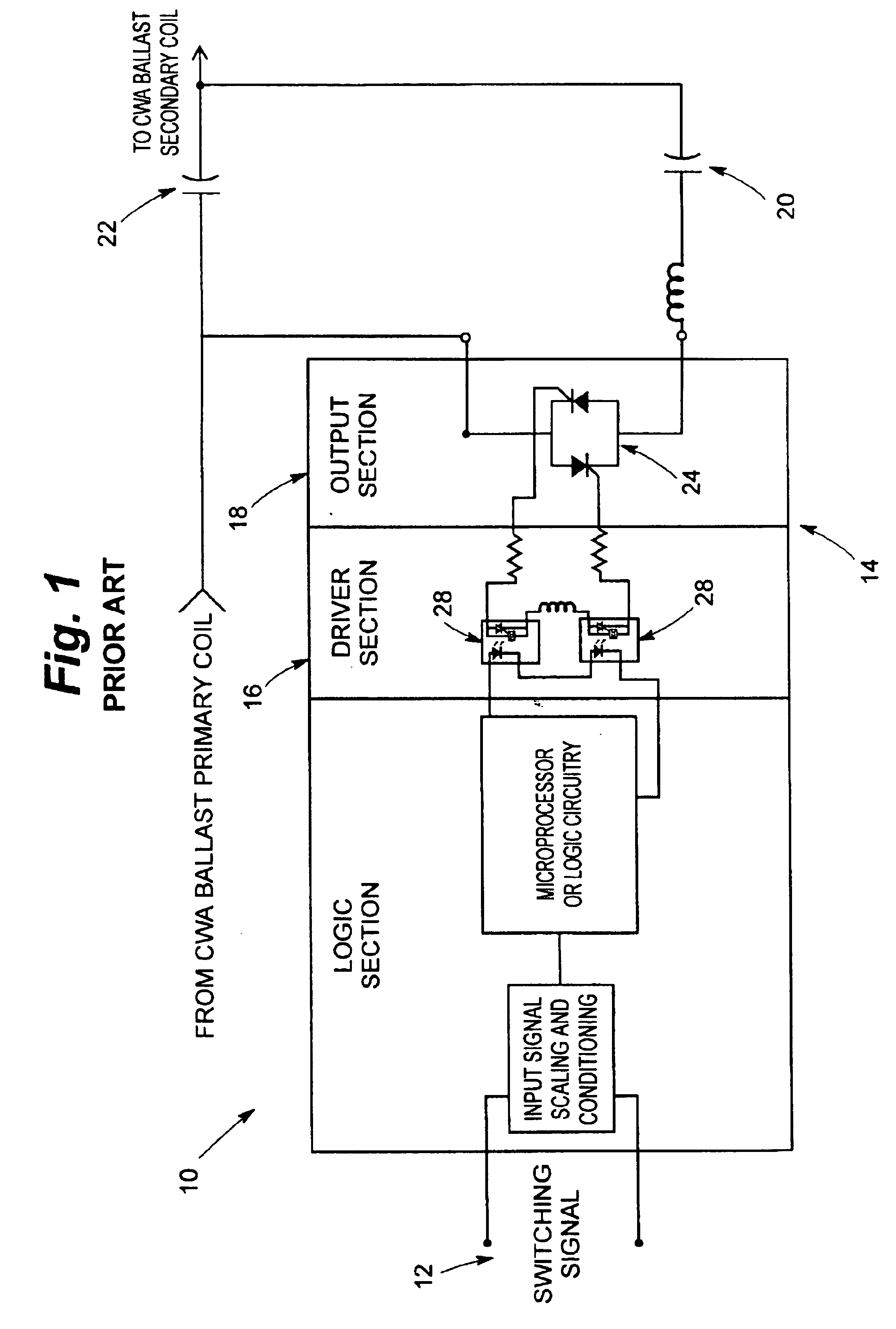
Referring now to the drawings and particularly to FIG. 1, a conventional switching circuit is seen at 10 to be operable from a switching signal supplied at 12 for control of a bi-level dimming system (partially shown in FIG. 1) utilizing high intensity discharge lamping (not shown in FIG. 1). The circuit 10 comprises an electronic relay seen generally at 14 to have a driver section 16 and an output section 18. The electronic relay 14 essentially takes the form of a conventional electronic switch. In the circuit 10, a capacitor 20 is switched in and out of parallel with a capacitor 22. The output section 18 of the electronic relay provides this switching function. In operation, a maximum peak voltage rating must be in excess of the combined peak voltage of the capacitors 20, 22. The parallel capacitors 20, 22 in prior art systems are switched on conventional CWA or c...


PUM


Abstract

Switching of parallel capacitors in an HID bi-level lighting control system is accomplished through use of transient voltage suppression across an electronic relay for discharge of residual charge from a switched capacitor when combined peak voltage exceeds clamping voltage, thereby allowing maximum switch voltage rating to be lower than is possible through the use of conventional switching methods and circuitry. The invention contemplates method and apparatus permitting capacitive switching at voltage levels higher than are possible in conventional capacitive switching arrangements including capacitive switching arrangements used in lighting control systems.

Description

BACKGROUND OF THE INVENTION1. Field of the InventionThe invention relates to HID bi-level lighting control systems and particularly to the switching of parallel capacitors in such systems using voltage suppression.2. Description of the Prior ArtBi-level dimming systems using high intensity discharge lamps are commonly available in the art, prior systems typically functioning through switching of parallel capacitors on constant wattage (CWA) ballasts. In prior systems, switching has been preferably accomplished through use of electronic zero-crossing switches. Output devices within such systems have typically been back-to-back SCR devices or TRIAC devices. In such a system, a switch must be able to sustain twice the peak voltage of a powered capacitor due to the fact that the switch opens at zero current, zero current being peak voltage for a capacitor. In the following half cycle, the voltage of the powered capacitor opposes that charge remaining on a switched-out capacitor. Althoug...

Claims


Application Information

Patent Timeline
Patent Type & Authority Patents(United States)
IPC IPC(8): H05B41/42H05B41/38
CPCH05B41/42Y10S315/04
Inventor HITCHCOCK, WILLIAM HENRY
Owner ABL IP HLDG
Why Eureka
Try Eureka