
System and method for quantitative measurements of a material's complex permittivity with use of near-field microwave probes

a near-field microwave and permittivity technology, applied in the field of measurement techniques, can solve the problems of difficult and often impractical accurate determination of these parameters, inability to accurately measure the permittivity of materials, and inability to achieve the effect of high accuracy and easy modification control

Inactive Publication Date: 2005-02-15
SEMICON PHYSICS LAB
View PDF10 Cites 26 Cited by
  • Summary
  • Abstract
  • Description
  • Claims
  • Application Information

AI Technical Summary

Benefits of technology

"The present invention provides a technique for quantitative measurements of material's complex permittivity using near-field microwave probes that are independent of the actual geometry of the probe's tip and the distance between the probe and the sample. This technique is based on a fast frequency sweep technique and a shear force based distance control mechanism. The invention also provides an algorithm for quantitative measurement of dielectric constants and dielectric loss tangent of a sample using the measured relative resonant frequency shift of the probe. The invention allows for precise measurements of the sample's material properties with near-field microwave probes."

Problems solved by technology

However, accurate determination of these parameters is difficult and often impractical, especially for very small tips of less than or on the order of a few microns in size which are of great importance for near-field microwave microscopy.
Though precise, the methods described in Peterson, et al., are relatively slow, since the total averaging time is on the order of or greater than 10 seconds assuming that at least 100 ms is required by the vector network analyzer (NWA) to acquire a single S parameter vs. frequency trace.
Moreover, it is likely that the resonant frequency is not going to be as stable as 10−8 or 10−10 during this period of time.
The existing methods for the resonant frequency and Q-factor measurements in the NFMM are generally deficient for the following reasons.
Scientific Instruments 70, 2783, 1999) may be performed with the synthesized source, however, this method results in a convolution of the two resonator characteristics, such as resonant frequency and Q-factor.
Frequency following techniques described in D. E. Steinhauer, et al., Applied Physics Letters, 71, 1736, 1997, are very fast (typical sampling rate is approximately 30 Hz), but neither precise nor accurate since the microwave source has to be used in the non-synthesized regime in order to lock a feedback loop.
Since this technique employs the synthesized source, it is fast and precise, however, the data obtained is generally a convolution of the sample topography and microwave properties.

Method used


Image

  • System and method for quantitative measurements of a material's complex permittivity with use of near-field microwave probes
  • System and method for quantitative measurements of a material's complex permittivity with use of near-field microwave probes
  • System and method for quantitative measurements of a material's complex permittivity with use of near-field microwave probes

Examples


Embodiment Construction

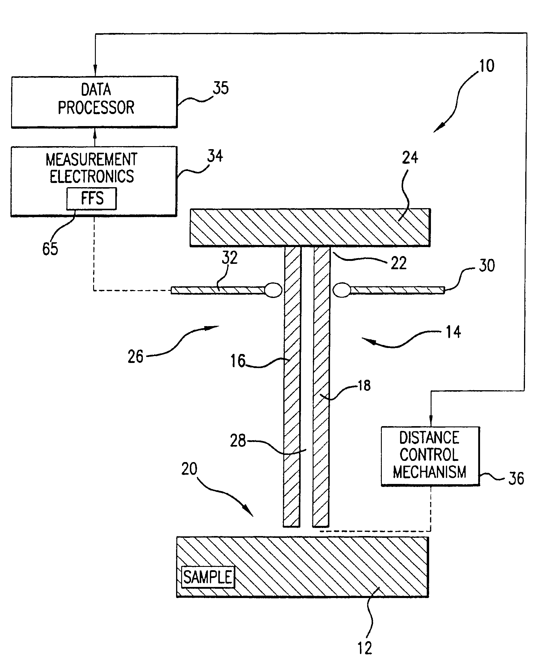
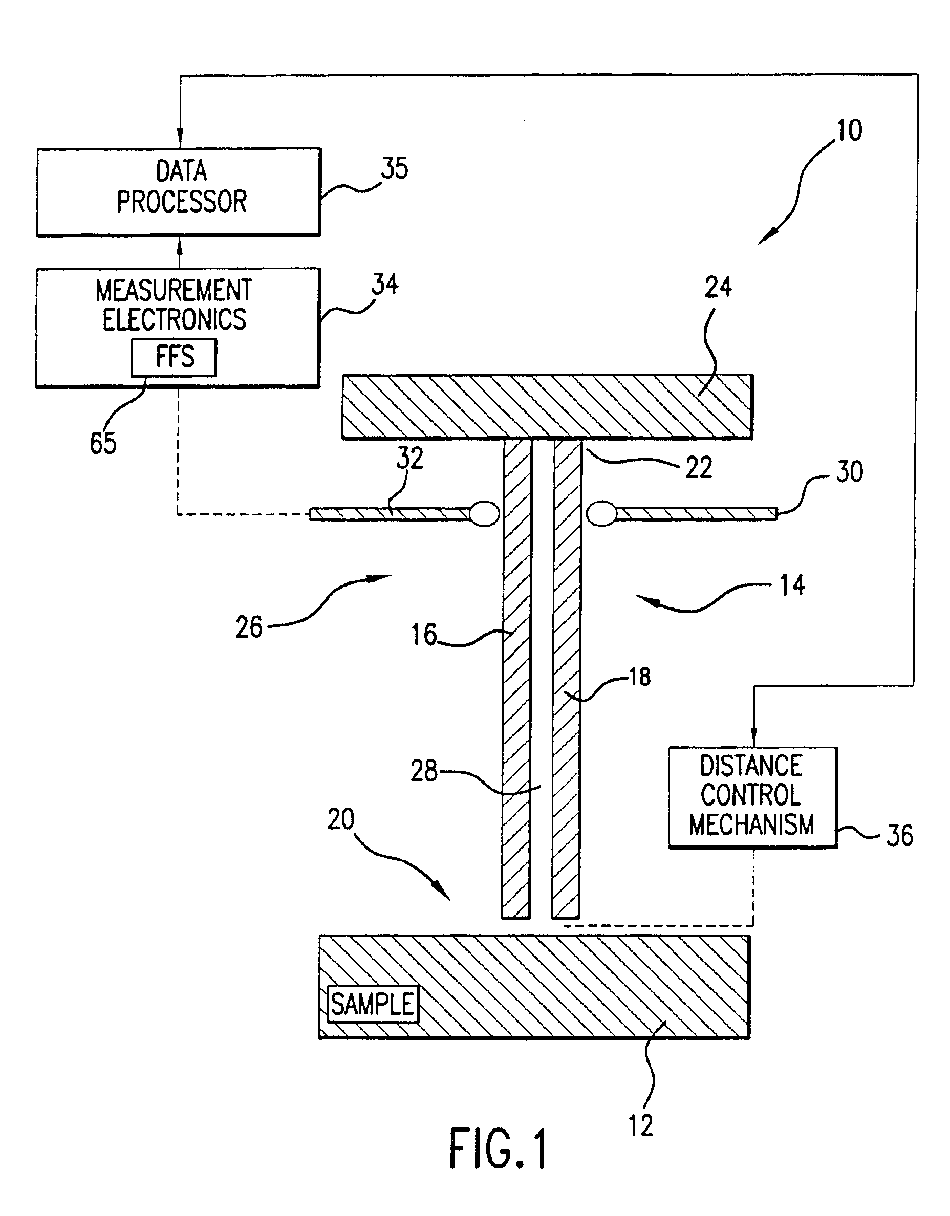
Referring to FIG. 1, there is shown a probe 10 for non-destructive determination of the complex permittivity of a sample 12 which is based on a balanced two conductor transmission line 14 which includes two spatially separated symmetrically arranged electrical conductors 16 and 18 of cylindrical, semi-cylindrical, rectangular, or similar type cross-section contour. The conductors may be formed out of copper, tungsten STM tips, gold, silver, or aluminum strips deposited onto a glass fiber as will be detailed in following paragraphs. A probing end 20 of the transmission line 14 is brought in close proximity to the sample 12 and an opposite end 22 of the transmission line 14 is either connected to electronics for the determination of a reflected signal's phase and magnitude, or to a terminating plate 24 to form a resonator structure 26 for the purposes described in the following paragraphs.

The probe 10 is primarily envisioned in two embodiments:A. In operation as a transmission line fo...


PUM

PropertyMeasurementUnit
complex permittivityaaaaaaaaaa
dielectric constantaaaaaaaaaa
relative resonant frequencyaaaaaaaaaa

Abstract

A method for measuring a material's complex permittivity is provided where a near-field microwave probe is positioned a predetermined distance from a first and a second standard sample for measuring a relative resonant frequency shift of the near-field microwave probe for standard samples. Based on measurements, calibration coefficients are calculated. A relative resonant frequency shift of the near-field microwave probe for a sample under study is measured by fast frequency sweep technique while the distance between the tip of the probe and the sample under the study is maintained nominally at the distance between the tip of the probe and each standard sample during a calibration procedure by a shear-force based distance control mechanism. Also, the change in the quality factor of the probe for unloaded and loaded resonator is measured. The dielectric constant of the sample under study is calculated using the resonant frequency shift and the change in the quality factor of the near-field microwave probe for the sample under study and the calibration coefficients obtained during the calibration procedure.

Description

FIELD OF THE INVENTIONThe present invention relates to measurement techniques. In particular this invention directs itself to a technique for highly localized measurements of complex permittivity of materials using near-field microwave probes. The concept is based on a balanced two-conductor transmission line resonator which provides confinement of a probing field within a sharply defined sampling volume of the material under study to yield a localized determination of the material's complex permittivity.More in particular, the present invention is directed to a method for quantitative measurement of a material's complex permittivity which does not require knowledge of probe geometry or the absolute distance from the tip of the probe to a sample under study.The present invention is additionally directed to a distance control mechanism employed for quantitative measurements of a material's complex permittivity to maintain the same distance between the tip of the probe and the measure...

Claims


Application Information

Patent Timeline
Patent Type & Authority Patents(United States)
IPC IPC(8): G01N22/00G12B21/02G12B21/00G01R27/06G01Q10/00G01Q60/18G01Q60/22G01Q60/46G01Q70/16
CPCB82Y20/00G01Q60/22B82Y35/00
Inventor TALANOV, VLADIMIR V.MORELAND, ROBERT L.SCHWARTZ, ANDREW R.CHRISTEN, HANS M.
Owner SEMICON PHYSICS LAB
Learn More