Sheet material fixing device

a technology of fixing device and sheet material, which is applied in the direction of recording apparatus, instruments, photomechanical apparatus, etc., can solve the problem of unnecessary pressure-reducing blower

Inactive Publication Date: 2005-02-15
FUJIFILM HLDG CORP +1
View PDF6 Cites 58 Cited by
  • Summary
  • Abstract
  • Description
  • Claims
  • Application Information

AI Technical Summary

Benefits of technology

In the sheet material fixing device in this case, some of the pressing portions press one end of the sheet material against the peripheral surface of the rotating member, whereas the other pressing portions press the other end of the sheet material against the peripheral surface of the rotating member. Moreover, as described above, each pressing portion can press the sheet material uniformly against the peripheral surface of the rotating member. Thus, when the rotating member is rotated, floating-up of the sheet material from off of the peripheral surface of the rotating member due to centrifugal force and against the pressing force of the pressing portion can be suppressed. The entire sheet material can be made to fit tightly to the peripheral surface of the rotating member.

Problems solved by technology

Thus, not only are the conventional many suction holes and suction grooves not needed, but also, a pressure-reducing blower is unnecessary.

Method used


Image

  • Sheet material fixing device
  • Sheet material fixing device
  • Sheet material fixing device

Examples


Embodiment Construction

An automatic printing plate exposure device 10, which relates to the embodiment and to which the sheet material fixing device of the present invention is applied, is shown in side view in FIG. 7.

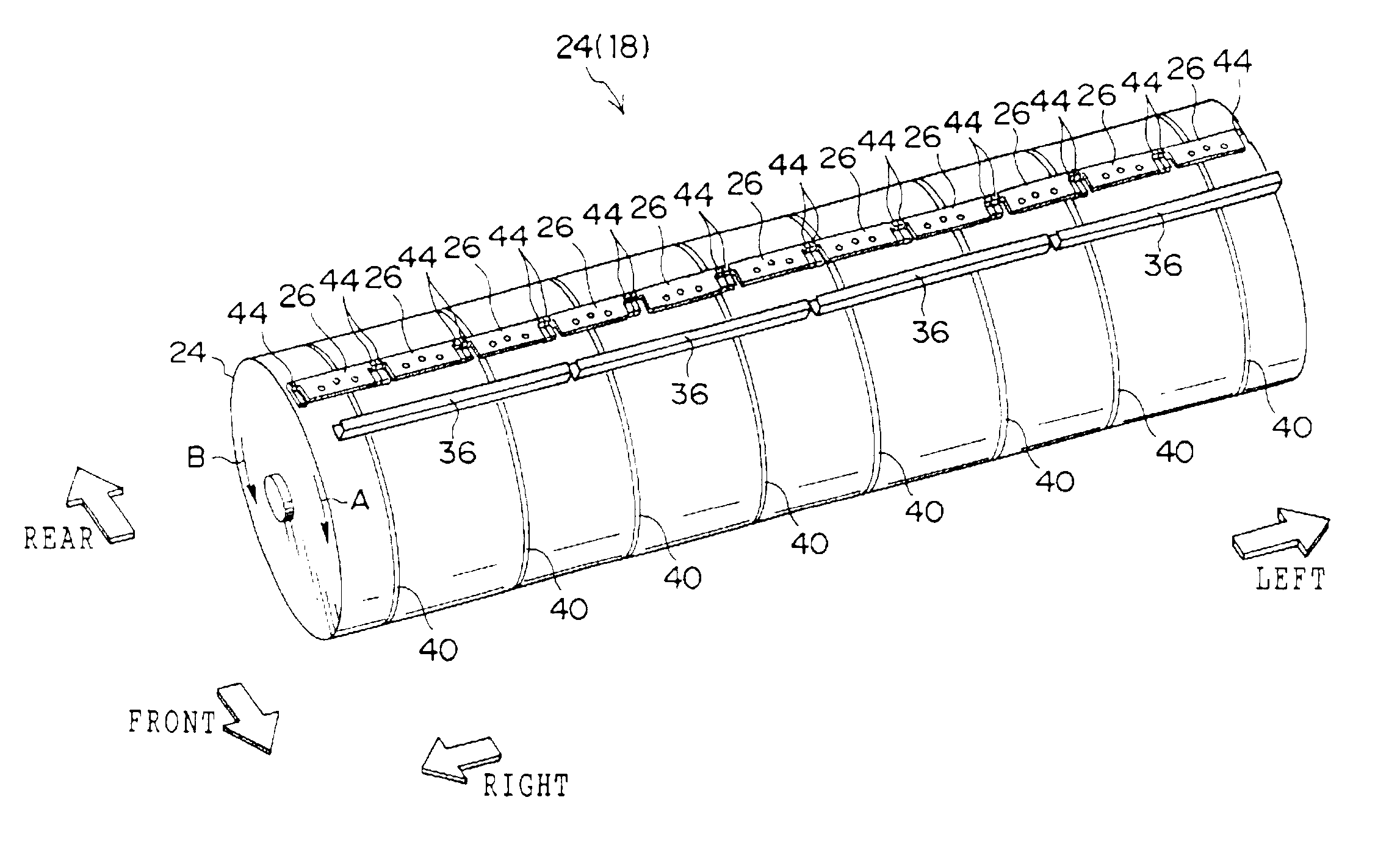
The automatic printing plate exposure device 10 relating to the present embodiment exposes (records) an image onto an image forming layer (e.g., photosensitive layer or heat-sensitive layer) on a support of a printing plate 12 which is a photopoly plate or a thermal plate or the like and which serves as a sheet material. The automatic printing plate exposure device 10 is divided into a conveying guide unit 14, a punching section 16, and an exposure section 18. The punching section 16 and the exposure section 18 are disposed in front of the conveying guide unit 14, and the exposure section 18 is disposed beneath the punching section 16.

The conveying guide unit 14 has a plate supplying guide 20, which is formed as a substantially rectangular flat plate, and a plate discharging guide 22, which ...


PUM

PropertyMeasurementUnit
elastic forceaaaaaaaaaa
shapeaaaaaaaaaa
massaaaaaaaaaa

Abstract

A device for fixing a sheet material to a cylindrical rotating member. Without using a suction mechanism and a vacuum, pressing portions of sheet material leading end clamps provided at a peripheral surface of the rotating member press the sheet material against the peripheral surface of the rotating member and fix the sheet material thereat. Each pressing portion has a region which deforms most due to centrifugal force generated by the rotating member. The pressing portion is formed in advance on the whole in a bow-like shape such that this region projects the most toward a center of the rotating member. Due to deformation caused by centrifugal force, the pressing portion changes from bow-shaped to planar, and uniformly presses the sheet material without a gap therebetween.

Description

BACKGROUND OF THE INVENTION1. Field of the InventionThe present invention relates to a sheet material fixing device which fixes a sheet material onto the peripheral surface of a rotating member.2. Description of the Related ArtPrinting plate exposure devices have been developed which record (expose) an image directly by a laser beam or the like onto an image forming layer (e.g., a photosensitive layer or a heat-sensitive layer) of a sheet-shaped printing plate (e.g., photopoly plate or a thermal plate).The printing plate exposure device is equipped with, for example, a rotating drum. The rotating drum is hollow cylindrical, and both ends thereof are closed. A printing plate is conveyed on the peripheral surface of the rotating drum. A pressure-reducing blower communicates with the interior of the rotating drum. A large number of suction holes and suction grooves are formed in the peripheral surface of the rotating drum. When a printing plate is being conveyed on the peripheral surfa...

Claims


Application Information

Patent Timeline
Patent Type & Authority Patents(United States)
IPC IPC(8): B41C1/10B41C1/00G03F7/24
CPCB41C1/1083
Inventor FUKUI, TAKASHI
Owner FUJIFILM HLDG CORP
Why Eureka
Try Eureka