
Non linear phase shift calibration for interferometric measurement of multiple surfaces

a multi-surface, phase shift calibration technology, applied in the field of interferometric profilometry, can solve the problems of insignificant errors, algorithm can be devised, and the psi of parallel plane objects cannot employ the production of the desired phase shift, so as to achieve the effect of effective calibration of inpu

Inactive Publication Date: 2005-02-15
PHASE SHIFT TECH INC A WHOLLY OWNED SUBSIDIARY OF ADE DBA ADE PHASE SHIFT
View PDF8 Cites 8 Cited by
  • Summary
  • Abstract
  • Description
  • Claims
  • Application Information

AI Technical Summary

Benefits of technology

It is a further object of this invention to provide a method for effectively calibrating the input to the phase shift driving mechanism of a wavelength tuned phase shifting interferometer to produce a constant phase shift speed for each interferogram during the acquisition of the interferometer.

Problems solved by technology

The relatively small number of frames employed is such that even if non-linear shifts between adjacent frames exist, the errors produced are insignificant.
Consequently, PSI for parallel plane objects cannot employ production of the desired phase shifts by varying the OPD directly.
The reason a simple variation of the OPD is insufficient is that the phase shift speeds (or signal frequencies) are the same for each superimposed interferogram; and it is unlikely that any phase algorithm can be devised to separate the individual signals and then assign them to their respective surfaces.
A significant disadvantage of the system and method disclosed in this patent is the requirement of the reversing of the orientation of the object between measurements.
If a measuring system cannot produce enough intensity frames, the algorithm may lose its ability to separate an interferogram of interest from a set of superimposed interferograms.
This measurement accuracy, however, is very difficult to achieve.
Even though there is a theoretical accuracy to this level, such measurement accuracy has not been achieved in industrial applications.
In addition, the high precision positioning requirements for accomplishing the types of results theoretically set forth in the Okada paper preclude the use of the Okada system and method in a production line operation.
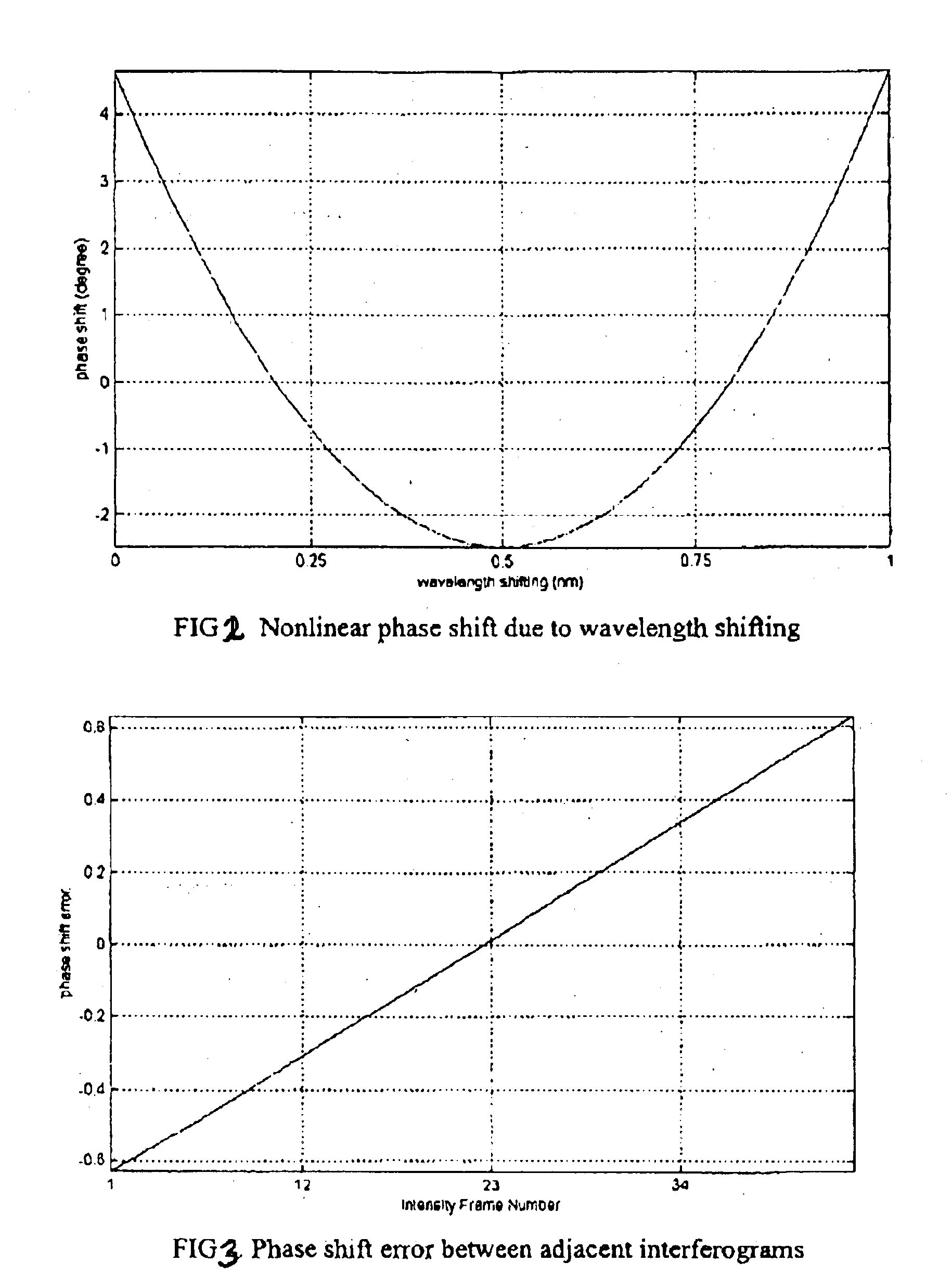
The reason such non-linear phase shift errors cannot be tolerated in the measurement of transparent objects with multiple reflective surfaces is that the phase shift speed for each underlying interferogram varies (or the signal frequency spreads), and it is unlikely that a phase algorithm can be devised to separate the individual signals and then assign them to their respective surfaces.
The phase shift errors result in ambiguities in the separation of the individual interferograms from the combined signals.
The separating errors, in turn, result in large phase errors on each surface as the information from the various surfaces is now mixed in a complicated manner.
Thus, the phase shift variation in Equation (1) may be large enough to induce a phase calculation error that is no longer negligible.
These additional error sources from currently available driving mechanisms actually result in much larger phase shift errors than those caused solely by wavelength changes themselves.

Method used


Image

  • Non linear phase shift calibration for interferometric measurement of multiple surfaces
  • Non linear phase shift calibration for interferometric measurement of multiple surfaces
  • Non linear phase shift calibration for interferometric measurement of multiple surfaces

Examples


Embodiment Construction

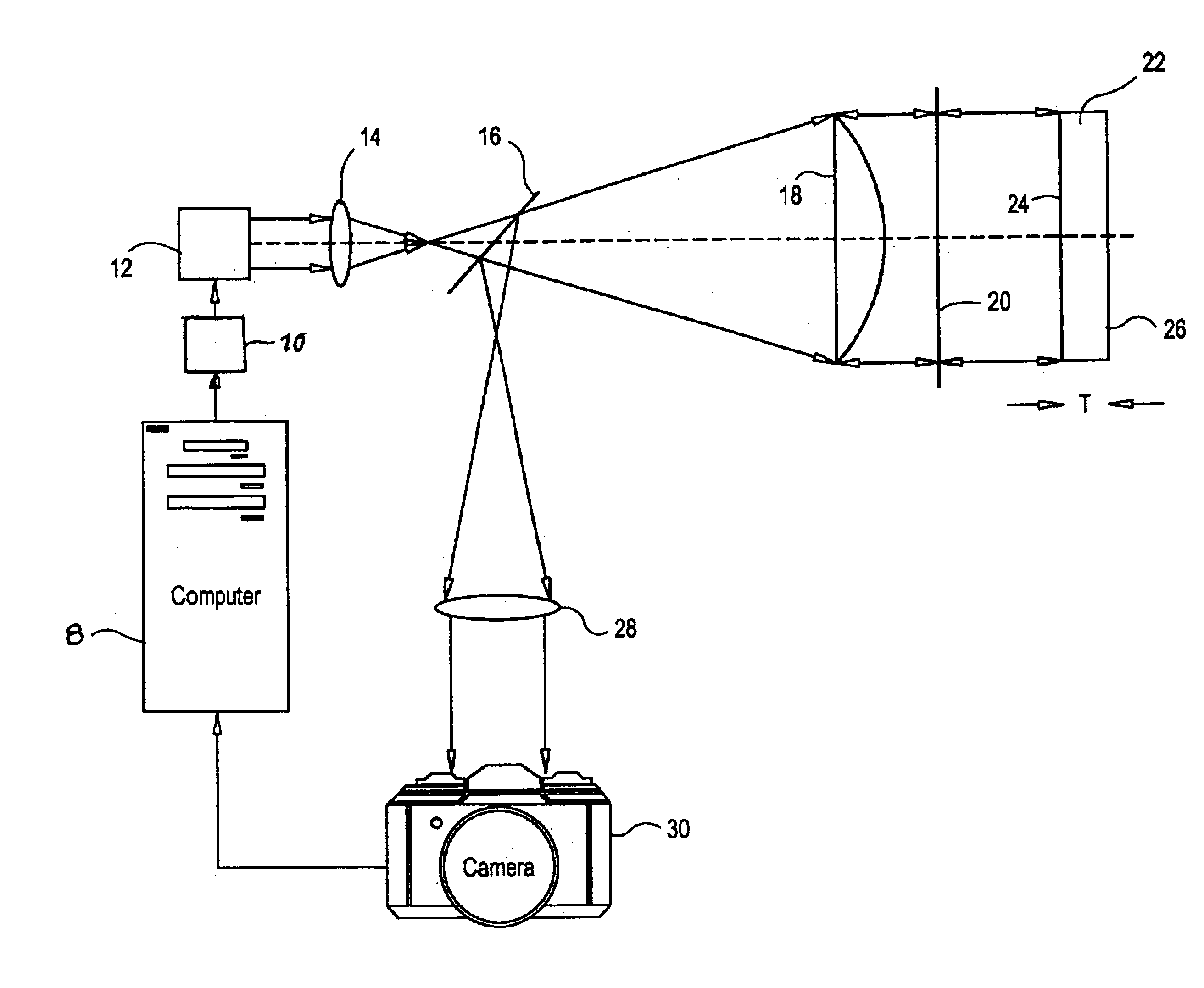
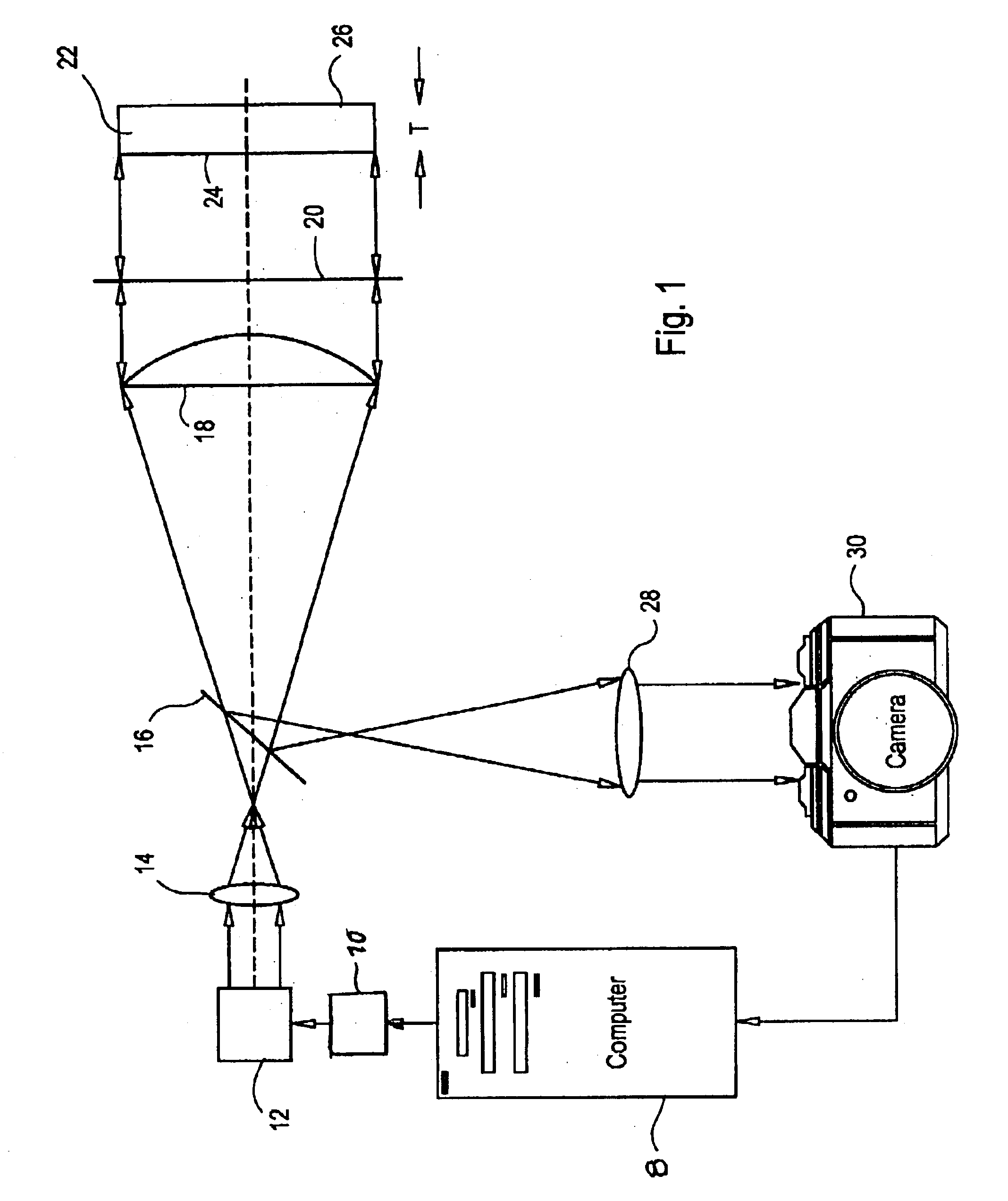
Reference now should be made to the drawings, which illustrate the implementation of a preferred embodiment of the invention in conjunction with an unequal path length interferometer. It should be noted that the optics which are employed in the implementation of the preferred embodiment of the invention are known; and these optics have been utilized, with varying degrees of success, for surface profiling of single and multiple surface objects in PSI systems.

The preferred embodiment of the method of the invention is illustrated as used in conjunction with an unequal path length interferometer in the form of the Fizeau interferometer of FIG. 1. It should be noted, however, that other unequal path length interferometers may also be used, such as a Twyman-Green interferometer. Such interferometers simultaneously extract phases of all of the individual interferograms from an set of intensity frames and record superimposed interferograms generated with wave fronts reflected from multiple ...


PUM


Abstract

A method and apparatus to linearize the phase shifts produced by the wavelength-varying driving mechanism of an interferometer used in phase shift interferometry for the measurement of multiple reflective surfaces first calibrates a sequence of physical values used as the input to the driving mechanism to produce a known linear or a known constant phase shift increment between any two adjacent interferograms. The calibration process, in essence, involves the determination of the sequence of physical values, such as the voltage change with respect to the time, through the process of iteration. This sequence then is used as an input to the phase shift driving mechanism for ongoing operation of the system, thereby compensating for non-linear characteristics of the system.

Description

BACKGROUNDThis invention pertains to the field of interferometric profilometry or, more precisely, to the field of wavelength tuned phase-shifting interferometry. Specifically, the invention is directed to a system and method utilizing a tunable coherent light source for the simultaneous measurement of multiple reflective surfaces to obtain precise surface height (or phase) information from a set of phase-shifted superimposed interferograms.Phase-shifting interferometry (PSI) has proven to be a highly accurate and efficient method for the measurement of reflective surfaces in a variety of applications including optical testing, surface profilometry, surface roughness estimation and surface displacement measurement. The fundamental concept of PSI is that the phase of an interferogram can be extracted accurately by acquiring a set of phase shifted interferograms (or intensity frames) with a constant phase shift between any two adjacent frames. The phase shifts can be produced either b...

Claims


Application Information

Patent Timeline
Patent Type & Authority Patents(United States)
IPC IPC(8): G01B11/24G01B9/02
CPCG01B11/2441G01B9/02072G01B9/02057G01B9/02004
Inventor TANG, SHOUHONG
Owner PHASE SHIFT TECH INC A WHOLLY OWNED SUBSIDIARY OF ADE DBA ADE PHASE SHIFT
Learn More