
Fast steering mirror

a mirror and fast technology, applied in the field of optical communication systems, can solve the problems of compromising the link, reaching the limits of the network infrastructure and technology, and achieve the effect of significant performance enhancement and cost reduction

Inactive Publication Date: 2005-02-15
PERTEX TELECOMM
View PDF4 Cites 34 Cited by
  • Summary
  • Abstract
  • Description
  • Claims
  • Application Information

AI Technical Summary

Benefits of technology

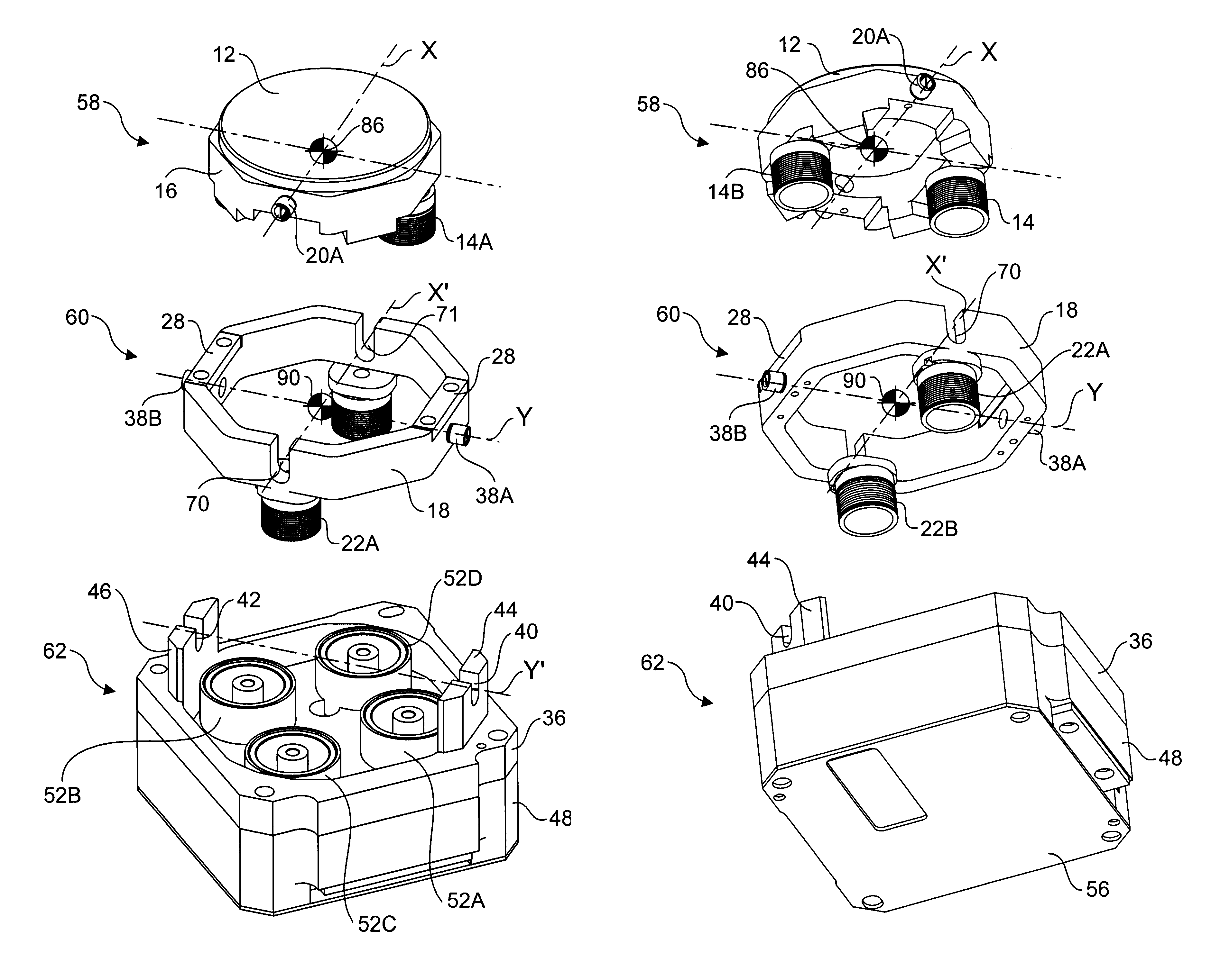
The present invention concerns a fast steering mirror for use in free space optical communication systems that provides significant performance enhancements and cost reductions when compared with existing fast steering mirrors. The fast steering mirror includes a gimbaled movement comprising an outer gimbal pivotally coupled to a base member and an inner gimbal pivotally coupled to the outer gimbal. A mirror that is posited by the fast steering mirror apparatus is coupled to the inner gimbal. A first pair of voice coil drivers including a pair of magnetized stators fixedly coupled to the base member and a pair of voice coils fixedly coupled to the outer gimbal are provided to enable the mirror to be pivoted about a first pivot axis X through rotation of the inner gimbal relative to the outer gimbal in response to selectable drive currents provided to the windings in the inner gimbal voice coils. Likewise, a second pair of voice coil drivers comprising a pair of magnetized stators coupled to the base member and a pair of voice coils coupled to the outer gimbal enable the outer gimbal to be rotated relative to the base member in response to selectable drive currents provided to the windings in the outer gimbal voice coils.

Problems solved by technology

Network users continue to demand faster networks, and as network demands continue to increase, existing network infrastructures and technologies are reaching their limits.
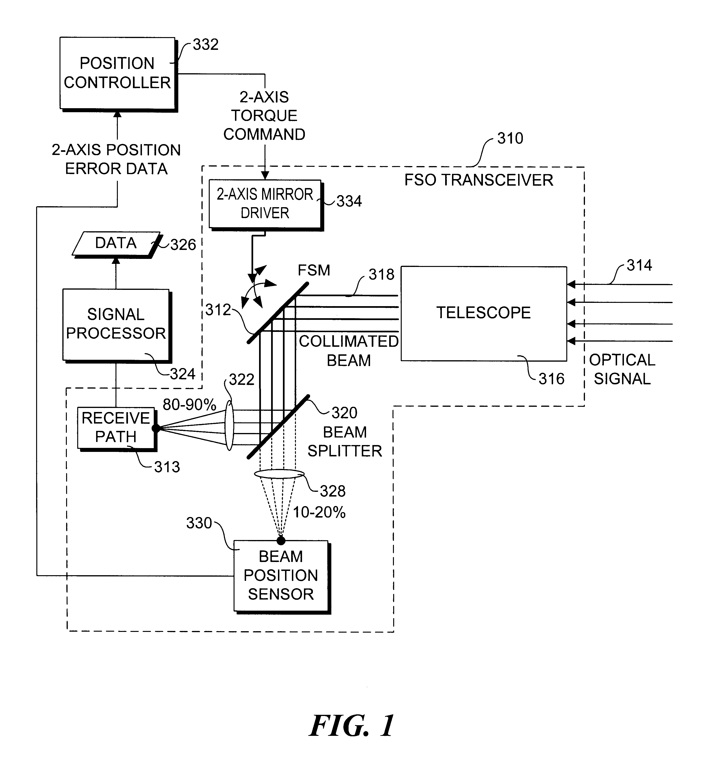
Thus, movement of the transmitter or receiver by even a small fraction of the divergence (or field-of-view) could compromise the link unless active tracking is employed.
Since high-speed communication channels utilize extremely sensitive detectors, such systems require equally sensitive tracking systems.

Method used


Image

  • Fast steering mirror
  • Fast steering mirror
  • Fast steering mirror

Examples


first embodiment

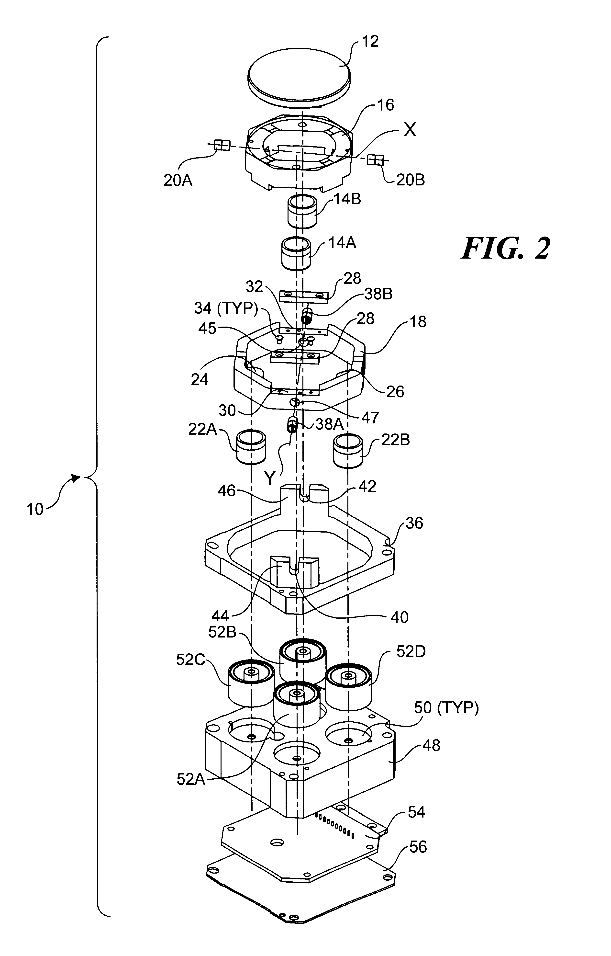
An exploded isometric view illustrating a fast steering mirror 10 in accordance with the invention is shown in FIG. 2. Fast steering mirror 10 includes a mirror 12 and a first pair of voice coils 14A and 14B that are mounted to an inner gimbal frame 16. The inner gimbal frame is pivotally coupled to an outer gimbal frame 18 via a first pair of flex pivots 20A and 20B, forming a first pivot axis X. A second pair of voice coils 22A and 22B are mounted to the underside of outer gimbal frame 18 via respective mounting pads 24 and 26, as well as a pair of counterweights 28, which are mounted within respective cutouts 30 and 32 using fasteners 34. Outer gimbal frame 18 is pivotally coupled to a gimbal support frame 36 via a second pair of flex pivots 38A and 38B to form a second pivot axis Y that is orthogonal to first pivot axis X. Respective flex pivots 38A and 38B include one end that is received by slots 40 and 42 defined in upright extensions 44 and 46 and secured with a structural a...

second embodiment

An exploded isometric subassembly view illustrating a fast steering mirror 110 in accordance with the invention is shown in FIGS. 7A and 7B. Many of the components in fast steering mirror 110 perform substantially similar functions to corresponding components in fast steering mirror 10; the reference numbers for these components share the last two digits in both embodiments. For example, fast steering mirror 10 includes a mirror 12 mounted to an inner gimbal frame 16, while fast steering mirror 110 includes a mirror 112 mounted to an inner gimbal frame 116.

In a manner similar to fast steering mirror 10, the primary subassemblies of fast steering mirror 110 include an inner gimbal assembly 102, an outer gimbal assembly 104, and a base assembly 106. Inner gimbal assembly is pivotally coupled to outer gimbal assembly 104 via a pair of flex-pivots 120A and 120B to create a first pivot axis X. Similarly, outer gimbal assembly 104 is pivotally coupled to base assembly 106 via a pair of fl...


PUM


Abstract

A fast steering mirror for use in free space optical communication systems. The fast steering mirror includes a gimbaled movement comprising an outer gimbal pivotally coupled to a base member and an inner gimbal pivotally coupled to the outer gimbal. A mirror that is posited by the apparatus is coupled to the inner gimbal. A first pair of voice coil drivers including a pair of magnetized stators fixedly coupled to the base member and a pair of voice coils fixedly coupled to the outer gimbal are provided along with a second pair of voice coil drivers comprising a pair of magnetized stators coupled to the base member and a pair of voice coils coupled to the inner gimbal. Selectable drive currents may be provided to the windings in the voice coils to position the mirror. In one embodiment, the fast steering mirror further includes a reference position seek mechanism.

Description

TECHNICAL FIELDThe present invention relates generally to optical communication systems, and in particular, to a fast steering mirror for use in free-space optical communication systems.BACKGROUNDWith the increasing popularity of wide area networks, such as the Internet and / or World Wide Web, network growth and traffic have exploded in recent years. Network users continue to demand faster networks, and as network demands continue to increase, existing network infrastructures and technologies are reaching their limits.An alternative to existing hardwire or fiber network solutions is the use of wireless optical telecommunications technology. Wireless optical telecommunication systems, also known as “free-space optical” (FSO) communication systems, utilize beams of light, such as lasers, as optical communications signals, and therefore do not require the routing of cables or fibers between locations. Data or information is encoded into a beam of light, and then transmitted through free...

Claims


Application Information

Patent Timeline
Patent Type & Authority Patents(United States)
IPC IPC(8): G02B7/182
CPCG02B7/1821
Inventor WITT, JOHN D.ANDERSON, TYLER M.
Owner PERTEX TELECOMM
Learn More