Coplanar camera scanning system

a scanning system and coplanar camera technology, applied in the field of optical scanning system, can solve the problems of increasing production costs, creating annoyance and possible danger for workers working in the vicinity of scanning system, and so on

Inactive Publication Date: 2005-02-15
DATALOGIC AUTOMATION
View PDF9 Cites 134 Cited by
  • Summary
  • Abstract
  • Description
  • Claims
  • Application Information

AI Technical Summary

Benefits of technology

[0008]Briefly stated, the present invention provides an optical scanning system which uses a light source to provide an illumination stripe that is coplanar to a camera lens and light sensor for barcode reading applications. The light source may be coplanar to the lens axis and light sensor, and preferably is formed from LEDs or other low power consumption illumination sources. The coplanar design provides adequate illumination for a large depth of field at low speeds.
[0009]In another aspect, the invention provides a scanning system in which the light source is shifted relative to the line of sight of the camera such that the illumination stripe remains coplanar with

Problems solved by technology

There are, however, several disadvantages to sodium lamp light sources.
First, due to their extreme brightness, sodium lamps can create an annoyance and possible hazard to workers working in the vicinity of the scanning systems.
Second, sodium lights require a large amount of AC power, thus increasing production costs.
Third, these ligh

Method used


Image

  • Coplanar camera scanning system
  • Coplanar camera scanning system
  • Coplanar camera scanning system

Examples


second embodiment

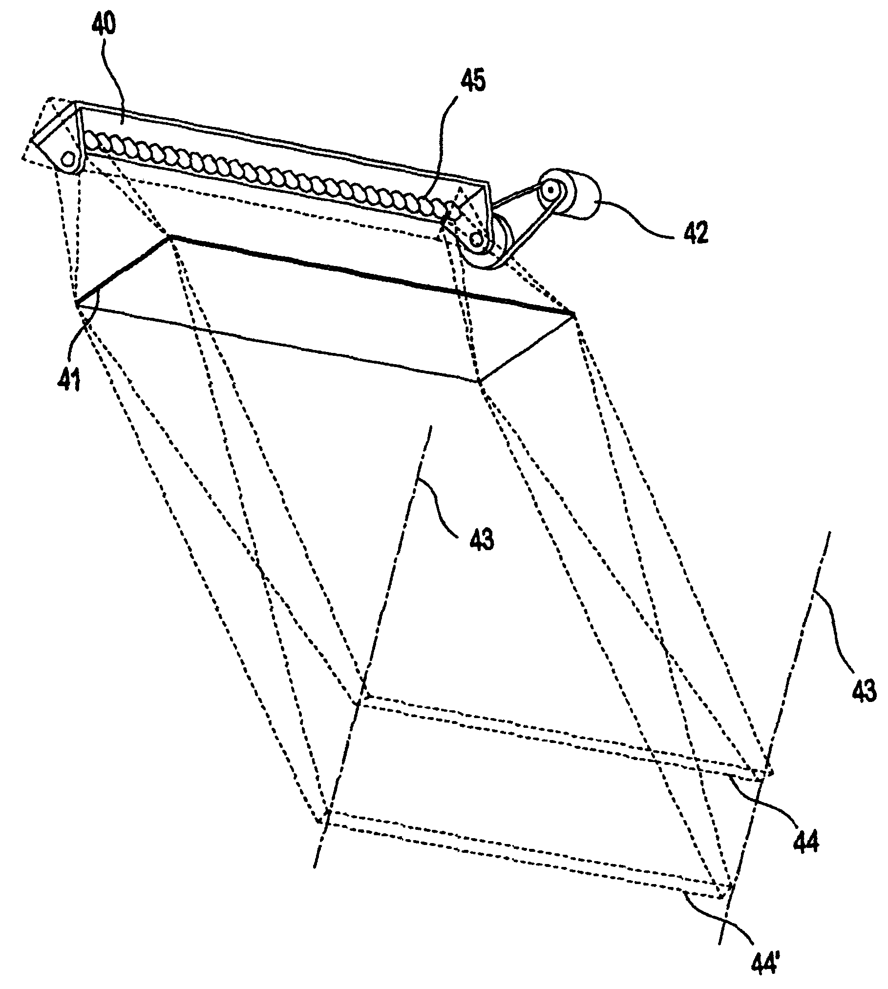
[0025]Referring to FIG. 4, the present invention uses an off axis light source 40 which is located off the camera lens axis and the linear array sensor, as represented by lines 43. The off axis light source 40 illuminates a target object by directing a beam of light onto its surface. However, the focused illumination stripe 44 is coplanar with the camera lens axis 43 and the linear sensor array at the required depth of field. The off axis light source 40 is preferably a movable array of LED sources 45 adapted to provide light to the target object. The invention, however, is not limited to this particular configuration or light source, as those skilled in the art will recognize alternative light sources from those described, such as semiconductor lasers, may be used.

[0026]The light source 40 may be focused by using an optional lens 41. The lens 41 may be any optical type lens, although a Fresnel lens is preferred. A light source positioner 42, preferably in the form of a controllable...

third embodiment

[0028]Referring to FIG. 6, the invention is shown which includes multiple arrays of light sources 51 which are located on one or more circuit boards 52 placed off-axis to the lens 53 and the linear array sensor. A range finder 50 is connected to the array of light sources 51. The range finder 50 determines distance between the camera and the target object. The distance data is sent to a controller which then powers on or off selected arrays of light sources 51 focused to a corresponding depth of field 55, 55′, 55″, 55′″ providing an illumination stripe 56, 56′, 56″, 56′″ coplanar to the camera lens axis 57. The camera 53 and lens 54 detect the reflected light from the illumination stripe to read required data from the object. Alternatively, all of the light sources 51 may be activated to provide the desired illumination stripe at any depth of field, eliminating the need for the distance to the target object


PUM


Abstract

A system for scanning objects having a linear array sensor, adapted to detect light input signals, is provided. A lens is optically connected to the linear array sensor, and is adapted to receive and transmit an optical image located in a field of view along a lens axis to the linear array sensor. A light source which generates an illumination stripe in general linear alignment with the lens axis is provided. A cylindrical lens is positioned between the light source and an object to be scanned. The cylindrical lens adapted to collect, transmit and focus light from the light source to form the illumination stripe.

Description

CROSS-REFERENCE TO RELATED APPLICATIONS[0002]This application is a continuation of U.S. application Ser. No. 09 / 810,204, filed Mar. 16, 2001 now U.S. Pat. No. 6,628,445, which claims the benefit of U.S. Provisional Application No. 60 / 190,273, filed Mar. 17, 2000.BACKGROUND[0003]The present invention relates generally to optical scanning systems. More particularly, this invention relates to a scanning system containing a camera using a coplanar light source.[0004]Various optical scanning systems have been developed for reading and decoding coded symbologies, identification of objects, comparison of objects, and measurement of objects. Each of these scanning systems utilizes either a non-coherent or coherent light source. Lighting is one of the key elements in obtaining good image quality. The intensity of light needed for scanning is directly proportional to the transport speed of the scanned object and the speed of the sensor. Generally, the faster an image is to be acquired, the mo...

Claims


Application Information

Patent Timeline
IPC IPC(8): G06K7/10G06V10/145H04N1/03
CPCG06K7/10722G06K7/10732H04N1/02815H04N1/02865H04N1/03G06V10/145
Inventor CHALEFF, EDWARD I.BROBST, THOMAS J.
Owner DATALOGIC AUTOMATION
Why Eureka
Try Eureka