

MEMS variable inductor and capacitor
a variable inductor and capacitor technology, applied in the field of electronic devices, can solve the problems of difficult implementation of magnetic materials in a mems device, impractical if not unrealizable, and the monolithic implementation of adjustable linear passive components employing conventional fabrication methods
- Summary
- Abstract
- Description
- Claims
- Application Information
AI Technical Summary
Benefits of technology
Problems solved by technology
Method used
Image

Examples
Embodiment Construction
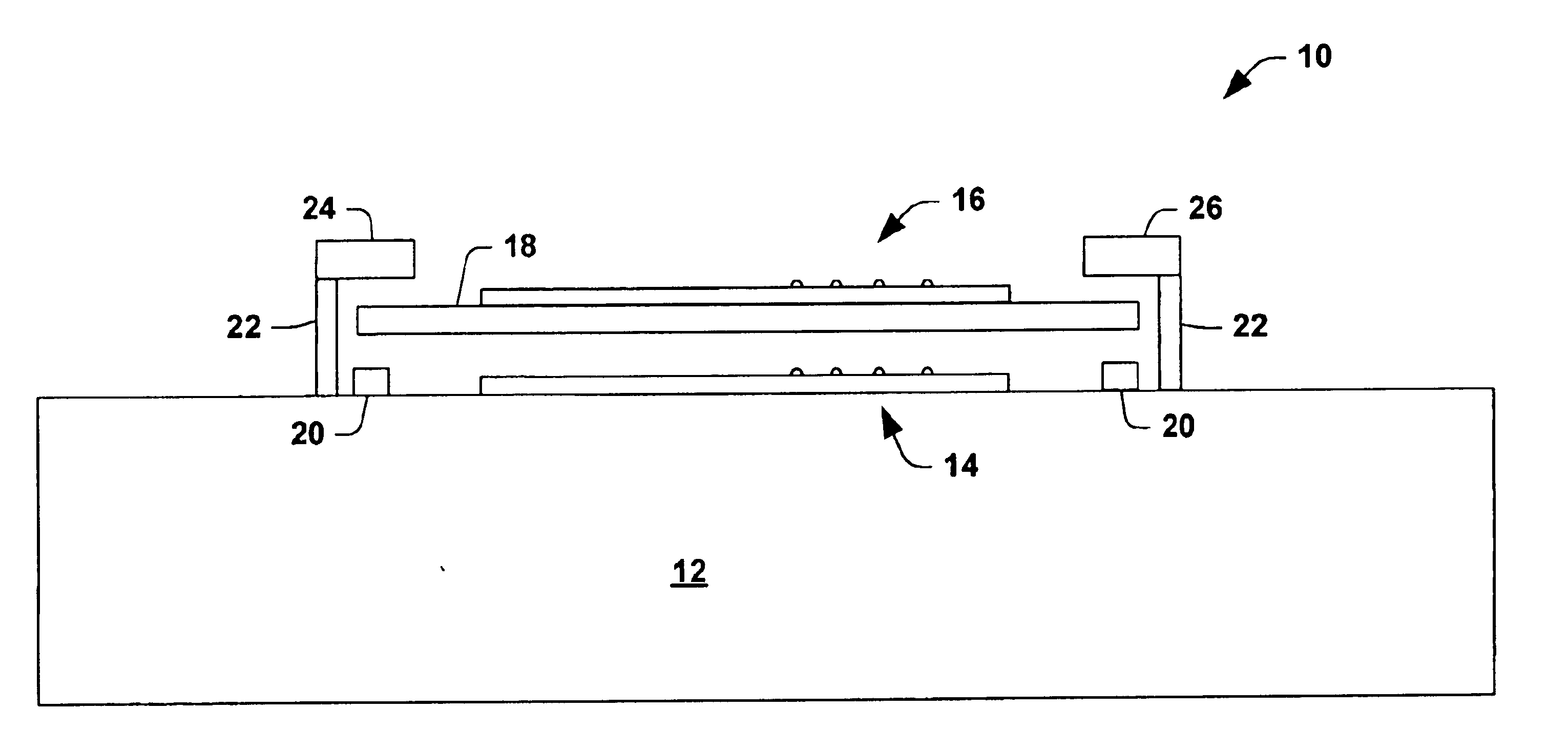
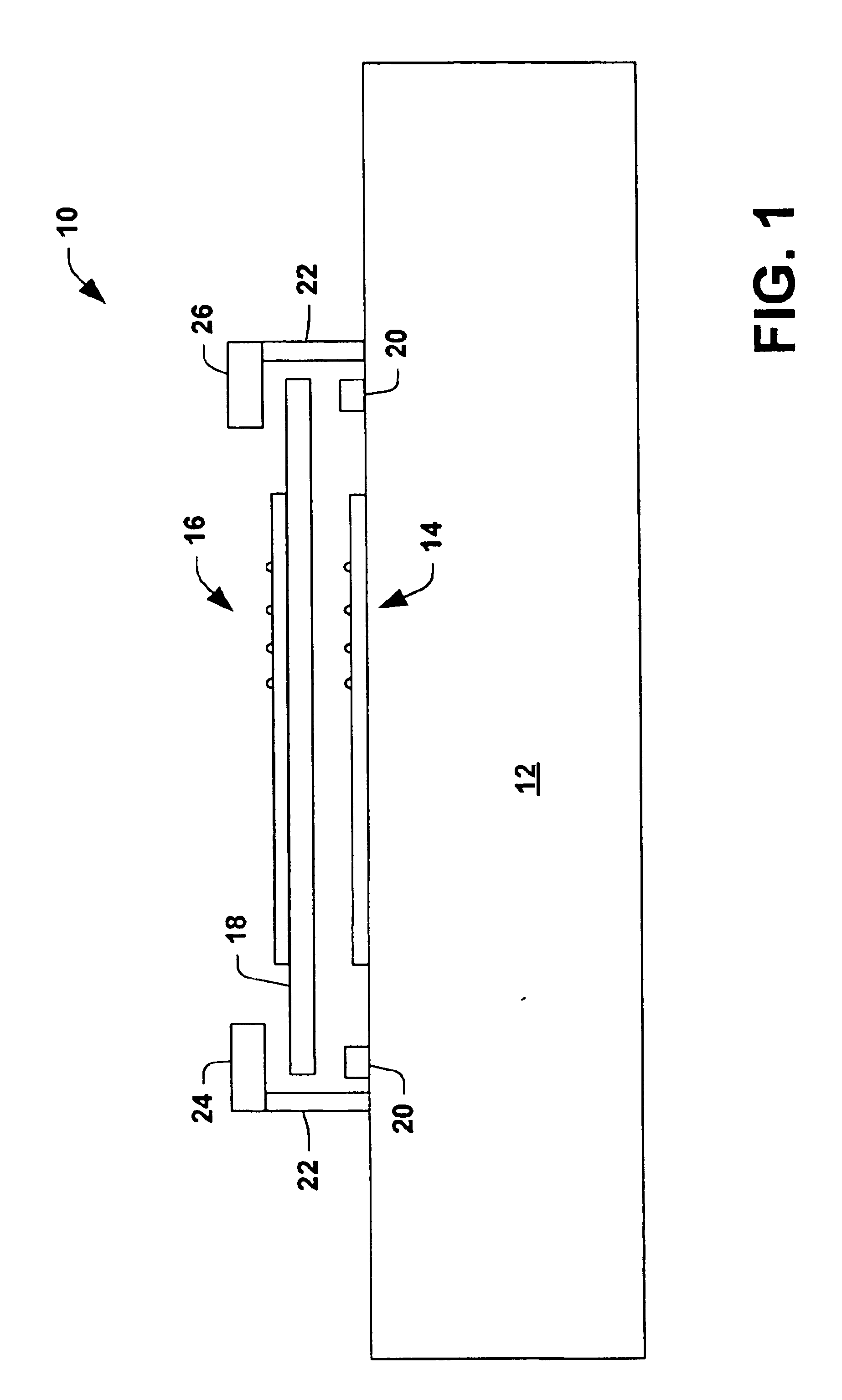
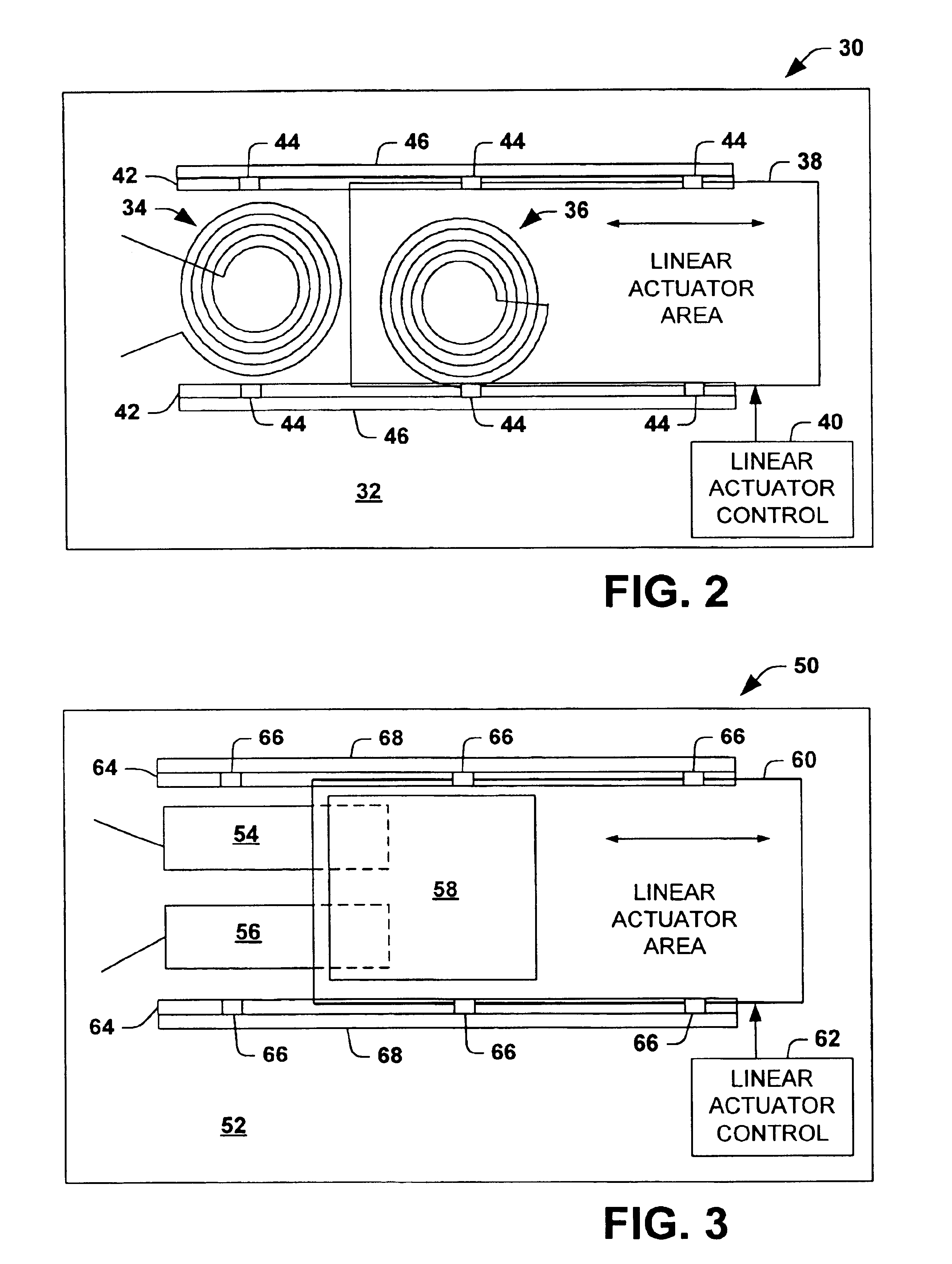
The present invention relates to variable passive components that can be provided on a MEMS device. The present invention employs a conductive portion on a low-profile sliding dielectric plate or sheet that cooperates with a conductive portion disposed on a substrate to provide a variable passive component. In one aspect of the present invention, the passive component is a variable inductor provided by moving a shorted spiral inductor formed on the dielectric sheet over a spiral inductor on the substrate with varying amounts of overlap causing varying inductance values. In another aspect of the present invention, the passive component is a variable capacitor that consists of a large conductive pad on a dielectric plate which slides over two adjacent pads on the substrate with varying amounts of overlap causing varying capacitance values.
The present invention employs a sliding in-plane MEMS motion to vary a passive component value (e.g., inductance or capacitance). The dielectric pla...
PUM
| Property | Measurement | Unit |
|---|---|---|
| conductive | aaaaa | aaaaa |
| inductance | aaaaa | aaaaa |
| electric field | aaaaa | aaaaa |
Abstract
Description
Claims
Application Information