Method and apparatus for automatic calibration of robots

a robot and automatic calibration technology, applied in the field of automatic calibration of robots, can solve the problems of manual calibration, manual calibration, and introduction of human error, and achieve the effect of reducing or eliminating the dependence on the ability of human operators and fast, accurate and reliable calibrations

Inactive Publication Date: 2005-02-15
APPLIED MATERIALS INC
View PDF8 Cites 41 Cited by
  • Summary
  • Abstract
  • Description
  • Claims
  • Application Information

AI Technical Summary

Benefits of technology

The present invention generally provides an apparatus and a method for automatic calibration of robots, particularly robots used in substrate processing systems. The automatic calibration apparatus and method according to the present invention provide fast, accurate and reliable calibrations while reducing or eliminating dependence on the ability of human operators. The automatic calibration apparatus and method are also adaptable for use with a variety of robots.
The method for calibrating a robot in a processing chamber according to the invention comprises: determining a useable free-space for the robot in a processing system; determining a distance between a position of a robot end effector and a target position in the useable free-space; and generating a path within the useable space from the position of the robot end effector to the target position using incremental displacements of the robot end effector that minimize the distance between the robot end effector and the target position. Preferably, the incremental displacements of the robot end effector is computed using a constrained gradient optimization process that calculates a path within the useable free space and avoids all obstacles and physical constraints within the system.

Problems solved by technology

However, there are several disadvantages to the manual calibration method.
First, manual calibration relies on the ability of a human operator to properly align elements and introduces the possibility of human error.
Also, the manual calibration method also requires a considerable amount of time when many locations are to be trained.
Thus, the manual calibration method has not been satisfactory for the high-precision robot training, particularly for robots used for substrate processing systems.

Method used


Image

  • Method and apparatus for automatic calibration of robots
  • Method and apparatus for automatic calibration of robots
  • Method and apparatus for automatic calibration of robots

Examples


example

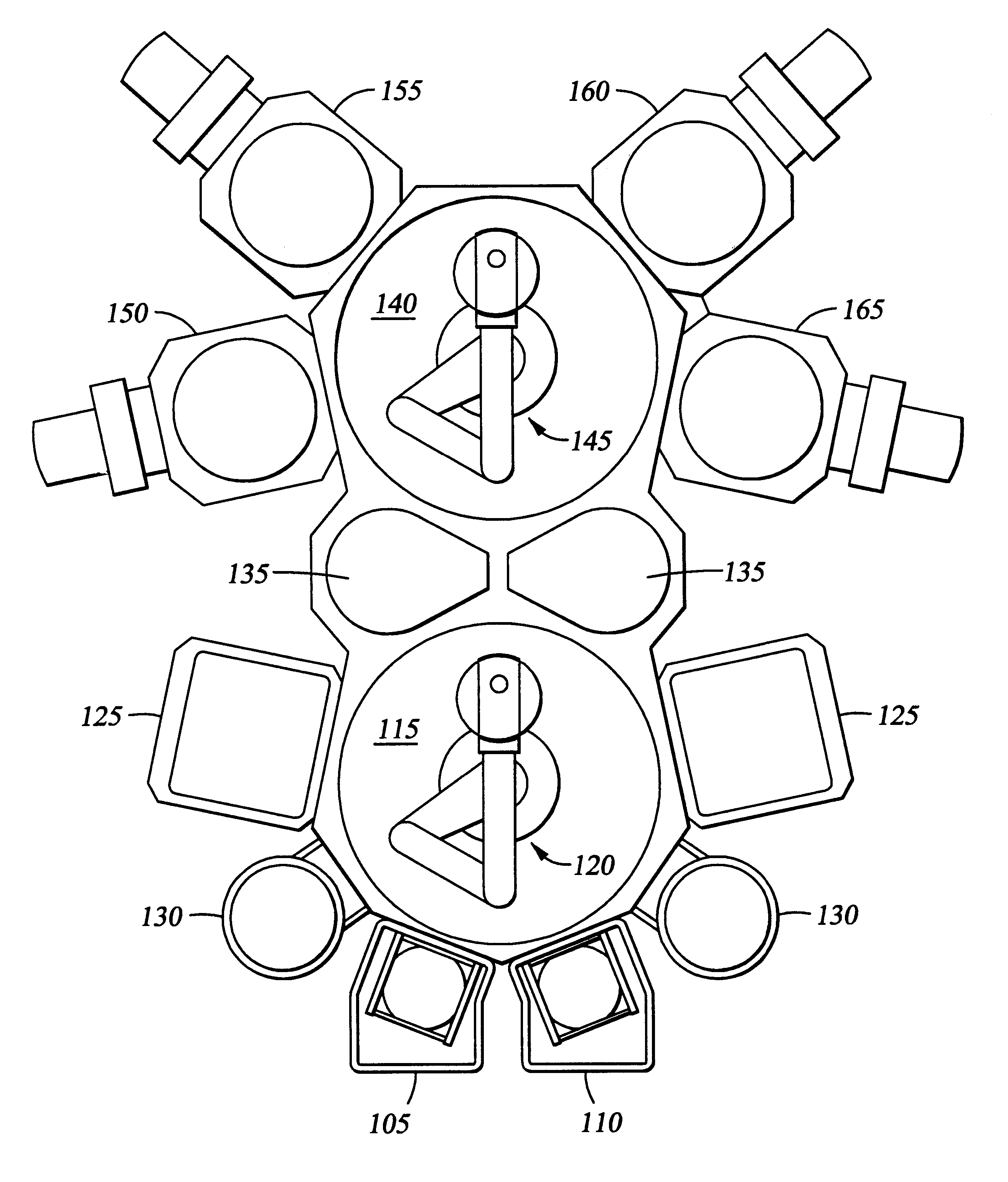
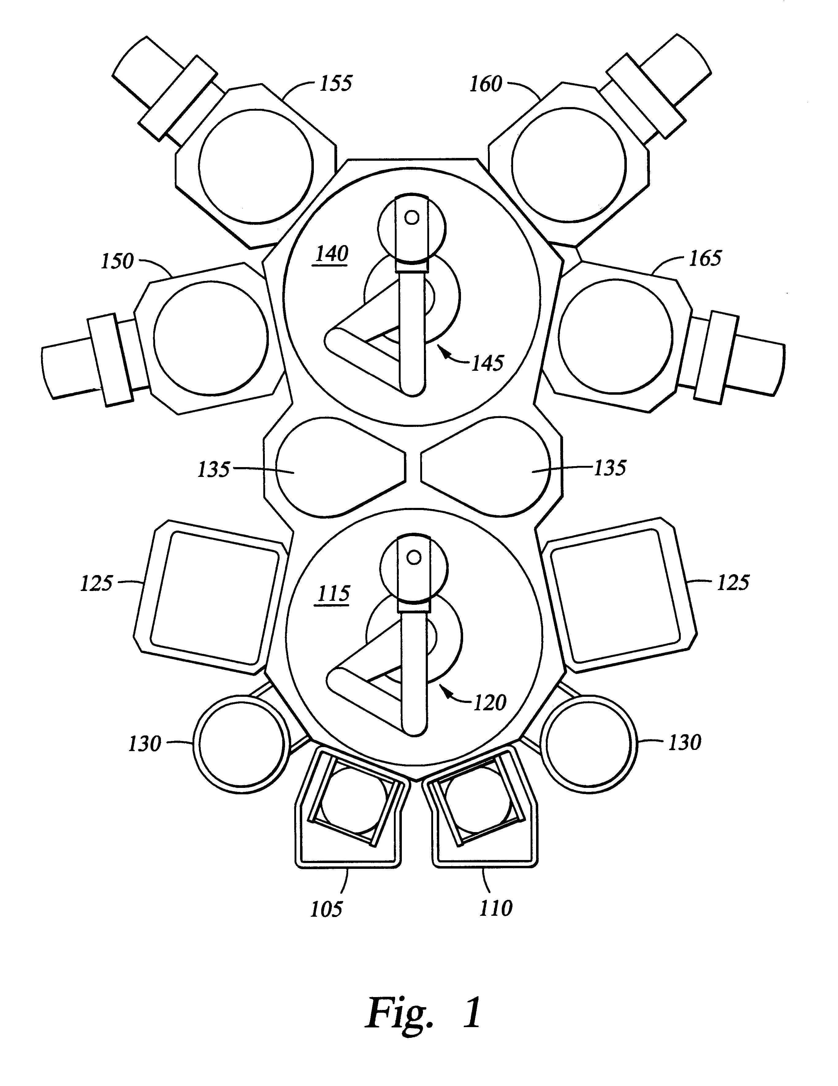
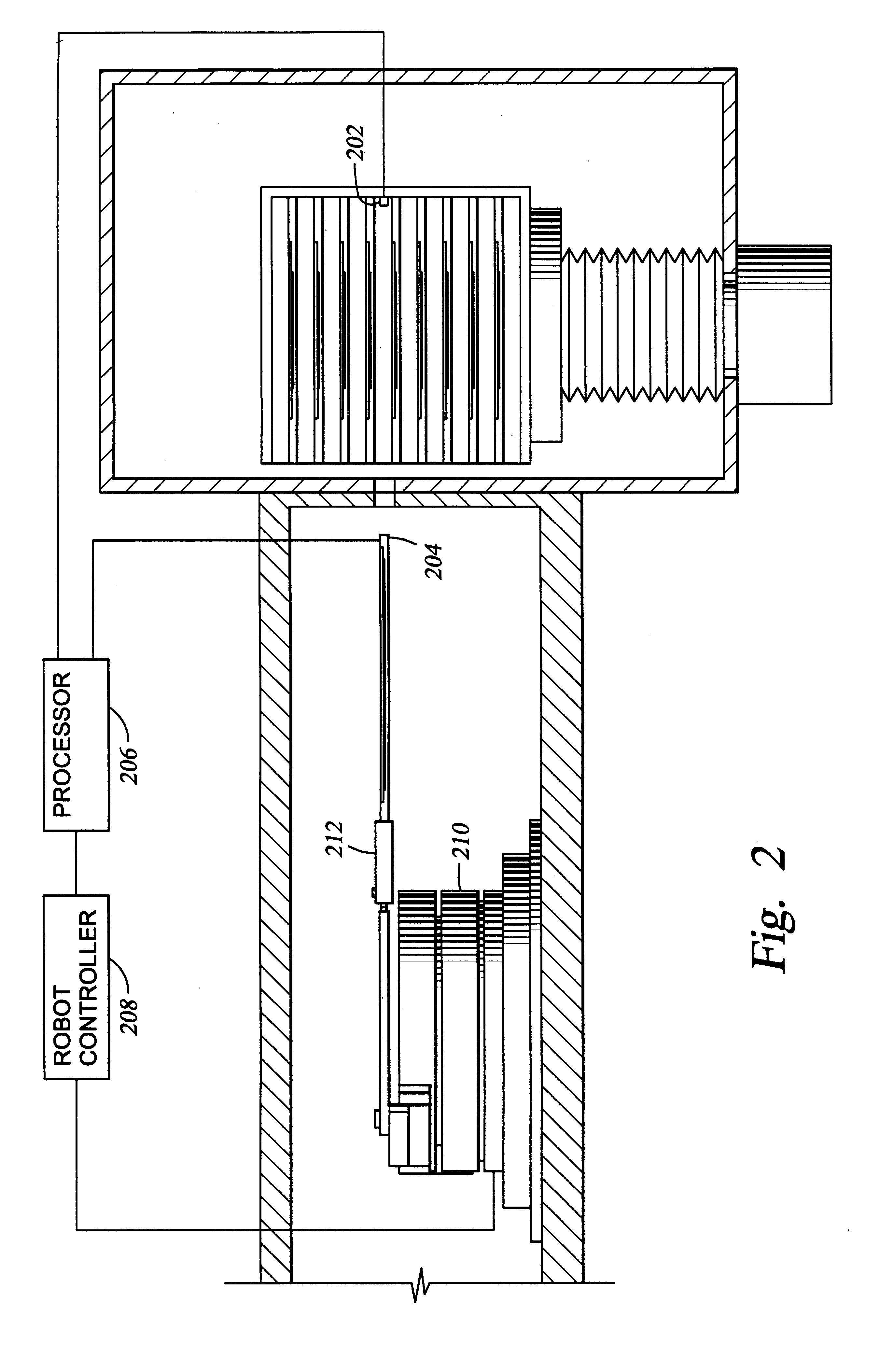
FIG. 3 is a schematic view of a central transfer chamber having a plurality of processing chamber attached thereto. The example describes a calibration of the robot from an initial rest position in a transfer chamber to a target position inside of a processing chamber 160. The auto-calibration of the robot is initiated by a measurement of the distance between the emitter 202 and the receiver 204 and their respective positions. The processor 206 receives the signals from the emitter 202 and the receiver 204 and processes the information using the auto-calibration algorithm. To simplify the optimization process of the auto-calibration algorithm, the free space of the processing system is defined by the operator as combinations of simple geometric forms instead of the calculated complete free space. As shown in FIG. 3, the user-defined free space G* of the transfer chamber and the load lock chamber is defined as the union of a circle 302 and a rectangle 304. By defining the free space ...


PUM


Abstract

An automatic calibration method and apparatus for robots, particularly robots used in substrate processing systems. The method for calibrating a robot in a processing chamber comprises: determining a useable free-space for the robot in a processing system; determining a distance between a position of a robot end effector and a target position in the useable free-space; and generating a path within the useable space from the position of the robot end effector to the target position using incremental displacements of the robot end effector that minimize the distance between the robot end effector and the target position. The apparatus for calibrating a robot in a processing system comprises: a sensor disposed at a location to be taught; a receiver disposed on a robot end effector; and a microprocessor connected to receive signals from the sensor and the receiver to determine a distance between the sensor and the receiver, wherein the microprocessor generates a path using incremental movements that minimizes the distance between the sensor and the receiver.

Description

BACKGROUND OF THE INVENTION1. Field of the InventionThe present invention generally relates to calibration of a robot. More particularly, the invention relates to automatic calibration of a robot in a processing system.2. Background of the Related ArtThe use of robots is convenient wherever and whenever the operations to be executed are high-precision, repetitive, tedious, stressful or otherwise hazardous to humans. Industries such as automobile manufacturing, production and assembly of integrated circuits, material handling and many others have employed industrial robots to improve efficiency and increase productivity.Many robots share the same basic design incorporating a base with one or more movable arms attached to the base. The arm typically includes a number of rigid bodies or segments connected by joints with a tool or an end effector usually mounted on the last segment. While the base is stationary, the joints are free to move in “revolute” or “prismatic” fashion. Revolute ...

Claims


Application Information

Patent Timeline
Patent Type & Authority Patents(United States)
IPC IPC(8): B25J9/16G05B19/401H01L21/00B25J9/00B25J9/10B25J9/22B65G49/07G05B19/404H01L21/677
CPCB25J9/1692G05B19/4015H01L21/67259G05B2219/45031G05B2219/39024B25J9/00
Inventor SUNDAR, SATISH
Owner APPLIED MATERIALS INC
Why Eureka
Try Eureka