Hierarchy of fault isolation timers

a timer and fault technology, applied in the field of computer servers, can solve problems such as system recovery, crash and loss, and irretrievably lost much valuable data, and achieve the effect of completing system recovery, and avoiding the loss of valuable data

Inactive Publication Date: 2005-02-15
VALTRUS INNOVATIONS LTD +1
View PDF13 Cites 17 Cited by
  • Summary
  • Abstract
  • Description
  • Claims
  • Application Information

AI Technical Summary

Benefits of technology

These and other objects, features and technical advantages are achieved by a system and method which deploys timers within devices in a distributed manner throughout a system or complex which includes CPUs and associated system chips, where the timers have a hierarchy of time-out values, and where the timers are able to independently experience time-out conditions generating a localized failure condition while enabling a remainder of the complex to continue operating. Preferably, a chip, device, or sub-system affected by the time-out or other error condition continues operating in a degraded or safety mode and communicates its condition to other chips and sub-systems so that the rest of the complex may continue operating while preferably bypassing the chip, device, or sub-system affected by the time-out condition.

Problems solved by technology

One problem with the above time-out mechanism is that a time out condition generally forces an entire network or complex of connected CPUs, to crash and lose all data associated with the system state in existence prior to the crash.
In this situation, system recovery may be accomplished only at a very basic stage with much valuable data having been irretrievably lost due to the time out condition.
Furthermore, the centralization of timer operation in the CPU leaves little data with which to identify a source or cause of the error which caused the time out condition.
Accordingly, re-occurrence of the event causing the time out may be difficult to prevent.
However, even with implementation of system chip based timers, a time-out condition will generally cause the entire network of computers to crash and lose all information associated with the machine state in existence just prior to the time-out condition.
And, as was the case with the previously discussed CPU-based timer approach, much data is irretrievably lost in upon occurrence of a time-out condition.
However, certain problems associated with earlier mentioned approaches remain.
Specifically, upon occurrence of a final time-out (for a transaction which will not be retried), the system will generally crash, and data associated with the machine state prior to the crash will generally be irretrievably lost.
Furthermore, the timing mechanisms are generally thinly scattered over a large number of devices, whether the timers are located exclusively in CPUs or are located in a combination of CPUs and system chips, such as memory and input / output (I / O) controllers.
Accordingly, a fault in an area of a computer network or complex may go undetected until the problem is substantial enough to cause a widespread system shutdown.
Accordingly, when a fault is encountered, a plurality of different timers may time out asynchronously in close temporal proximity to each other thereby causing the overall system to crash and making subsequent identification of the problem leading to the system crash very difficult.
It is further noted that in the prior art systems described above, a time out condition in one CPU or in one system chip may cause an entire complex of CPUs and associated system chips to fail or crash, thereby enabling a failure in 1% of a complex to disrupt operation of 100% of the complex.
Therefore, it is a problem in the art that the machine state of a computer system is lost upon occurrence of a time out condition.
It is a further problem in the art that only a very limited recovery operation is possible after occurrence of a time-out condition.
It is a still further problem in the art that identifying the timer whose expiration caused a system crash may be very difficult in the systems of the prior art.
It is a still further problem in the art that a transaction failure and associated time out condition in one chip of a complex may cause the entire complex to crash or fail.

Method used


Image

  • Hierarchy of fault isolation timers
  • Hierarchy of fault isolation timers
  • Hierarchy of fault isolation timers

Examples


Embodiment Construction

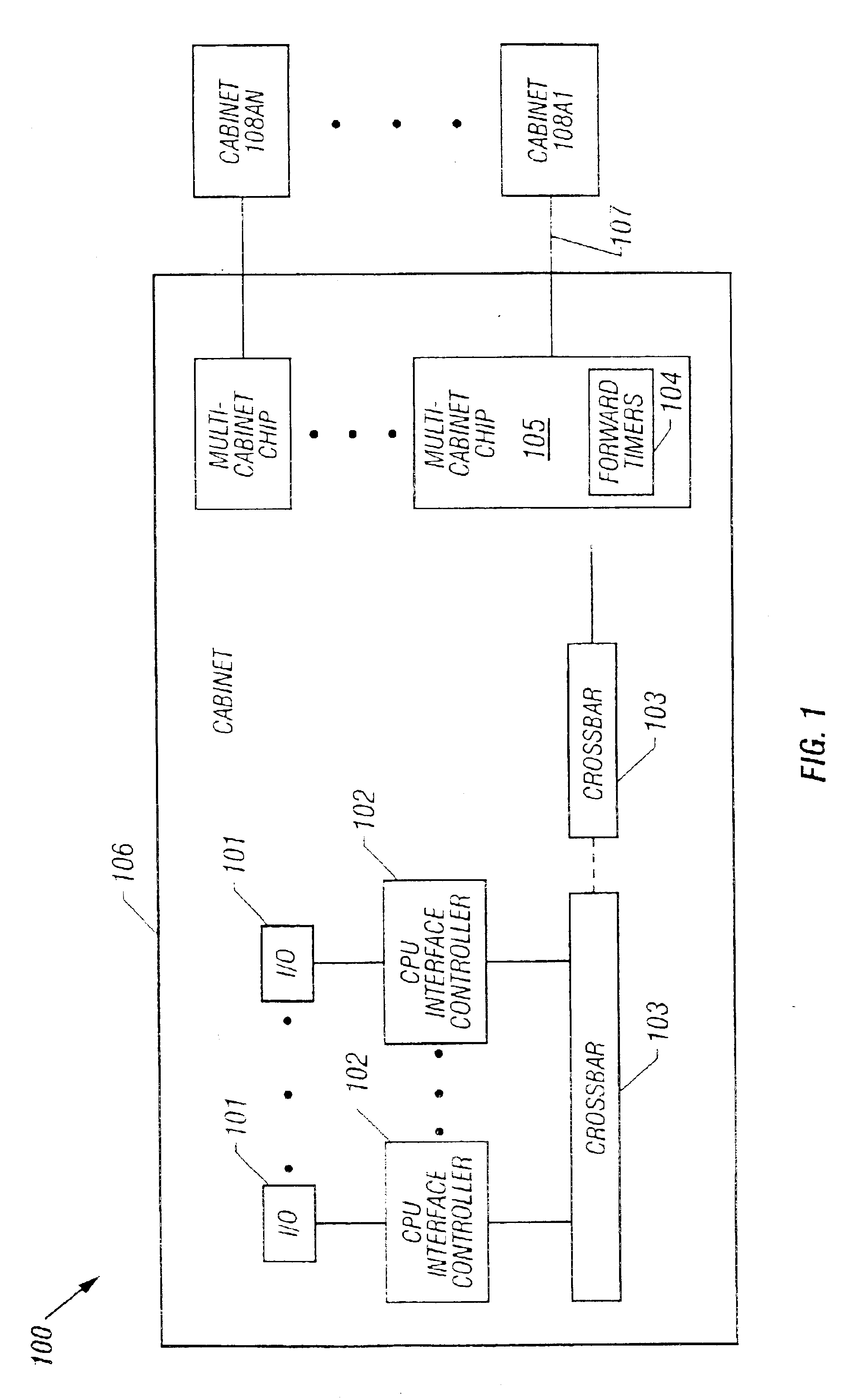
FIG. 1 depicts an operational building block of a complex of computers according to a preferred embodiment of the present invention. The operational building block depicted in the particular embodiment of FIG. 1 is a cabinet 106. It will be appreciated that the timing and failure isolation mechanism of the present invention may be implemented employing a range of system configurations and is not limited to deployment according to FIG. 1.

In a preferred embodiment, cabinets such as cabinet 106 may be employed as modular building blocks of an overall complex of computers. Cabinet 106 preferably includes multi-cabinet chip 105 which provides for a robust communication interface capable of conducting bi-directional communication with other like cabinets, such as cabinets 108A1 through 108AN, over cables, such as cable 107, as much as thirty feet in length. Cabinet 106 may be connected to any number of other cabinets employing a multi-cabinet chip, such as multi-cabinet chip 105, for each...


PUM


Abstract

In the present invention, a coordinated hierarchy of timing mechanisms preferably cooperate to report errors at different operational levels of a complex of computing devices. Preferably, each timer is able to identify a failure condition at its own level of operation and transmit a time-out condition to a higher level device which may also be a timer. Upon generation of a time-out condition, a system component experiencing a fault condition preferably continues to operate in a degraded mode, informs devices attempting to communicate with the faulty component of a status of the fault condition, and preferably proceeds to identify and correct a failure which caused the time out condition. The timers may be implemented in hardware or software.

Description

FIELD OF THE INVENTIONThis invention applies in general to computer servers and in particular to fault detection in computer servers.DESCRIPTION OF THE RELATED ARTIn computer systems which include a plurality of processors and associated peripheral equipment, a mechanism is generally implemented to track the status of requests and responses transmitted throughout a network or complex of such processors and other equipment. This mechanism is generally implemented so that when a request for data is sent, a time limit is imposed on satisfaction of the request by a CPU (Central Processing Unit) based counter. If the request is not satisfied within the time limit, a counter generally times out thereby triggering a high priority machine check which causes the computer network or complex to shut down, and initiating execution of recovery code by the CPU. Generally, the counter starts timing when a request for a transaction wins arbitration and is placed on a bus toward a designated destina...

Claims


Application Information

Patent Timeline
Patent Type & Authority Patents(United States)
IPC IPC(8): G06F11/00G06F11/30H02H3/05H04L1/22G06F1/14
CPCG06F11/0724G06F11/0757G06F11/0793
Inventor SHAW, MARK
Owner VALTRUS INNOVATIONS LTD
Why Eureka
Try Eureka