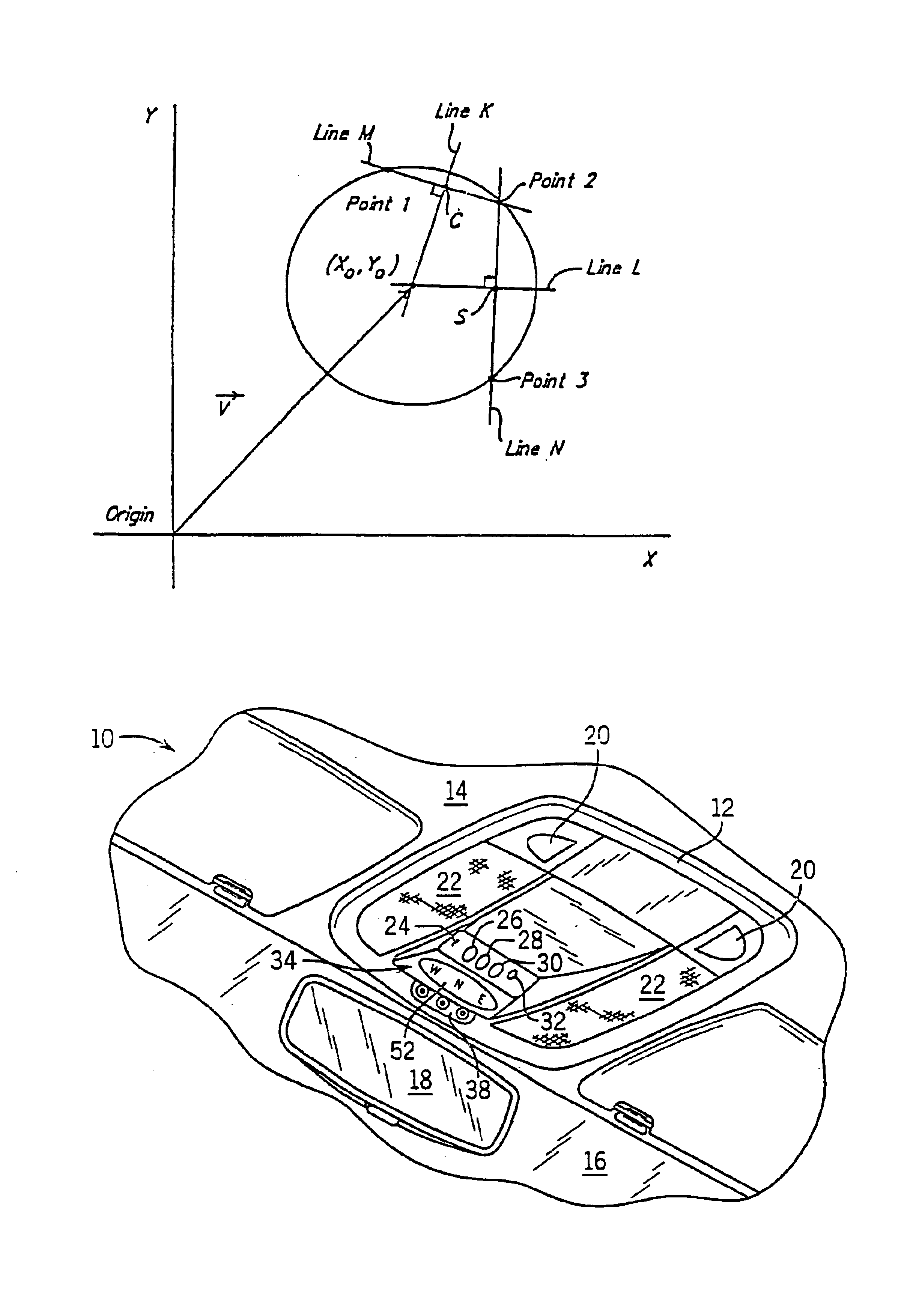
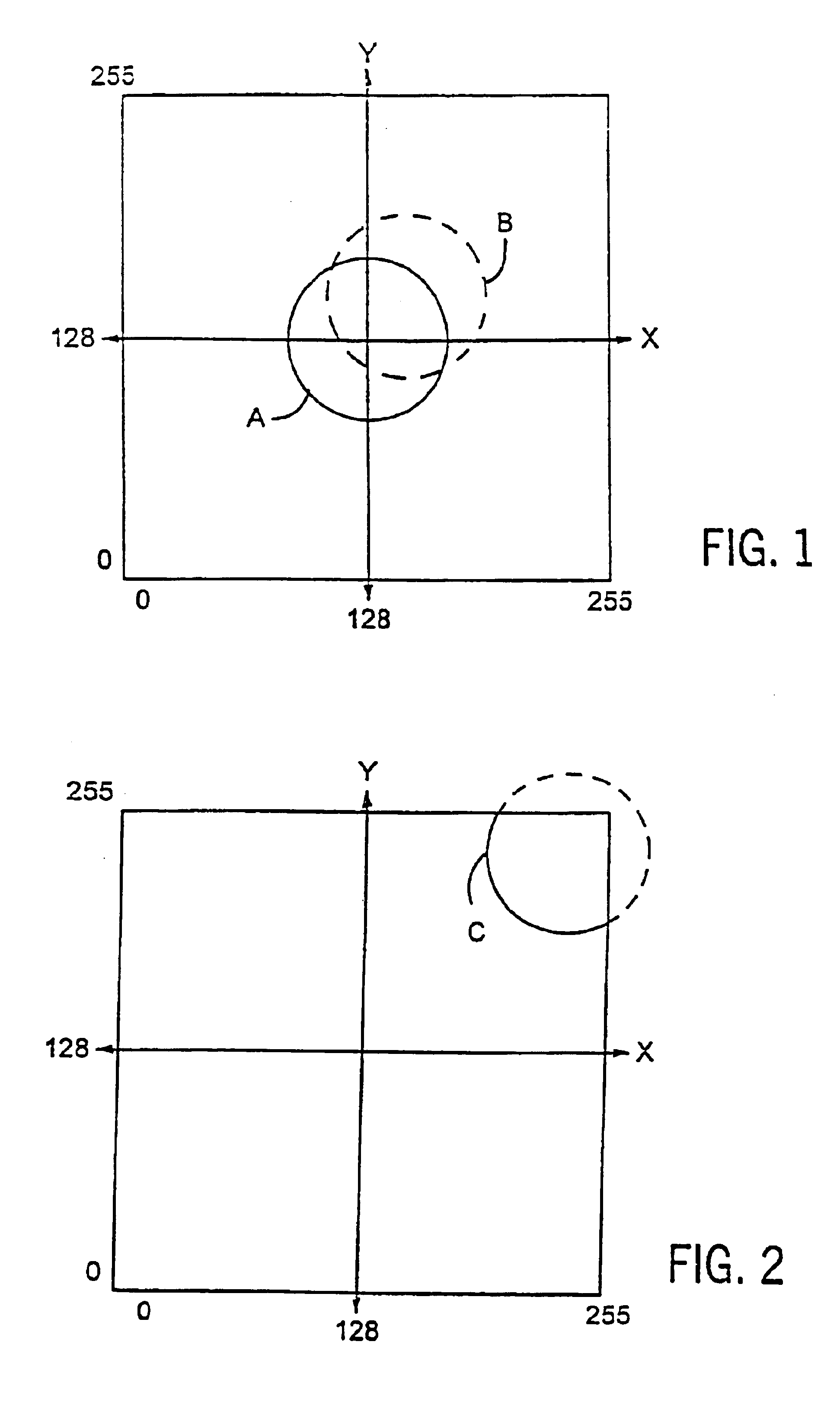
However, if the shift of sensor data is large enough such that the origin of the coordinate plane is not contained within the circular plot of sensor data created when the vehicle travels a 360° loop, then heading information cannot be calculated and the calibration system cannot provide correction in this somewhat unusual situation unless the sensor data experiences a subsequent shift that causes the origin of the coordinate plane to again be contained.
However, intermediate changes in vehicular
magnetism are possible which, while causing the plot of sensor data to shift and to not contain the origin of the coordinate plane when the vehicle completes a 360° loop, do not cause the sensor data to be plotted outside of the saturation limits.
Manual reinitiation would most likely occur when the operator notices that the displayed heading information is erroneous for an extended period of time.
Although the above-mentioned means by which to cause reinitiation of calibration enables the compass system to ultimately recover from changes in vehicular
magnetism of any magnitude, such reinitiation is considered a rather extreme measure since it requires the clearing of all prior sensor readings and calibration data.
Thus, until sufficient data is collected to calibrate the system, the system operates in an uncalibrated state.
As such, this compass system may be unable to adequately compensate for and recover from an abrupt and significant change in vehicular
magnetism caused by, for example, driving the vehicle near the electrical power feeders of
train or subway systems.
Thus, such an event may cause a substantial impairment of compass operation resulting in at least short-term erroneous heading information to be displayed until recalibration or reinitiation of the system is achieved.
Further, a particular problem with vehicular magnetism exists before sale of a new vehicle to a customer.
Although factory compensation of a new vehicle's compass has been standard practice for many years, current methods have proven to be inadequate.
For example, eliminating the magnetism requires special
degaussing equipment that is very expensive, and assigning the duty of manual calibration to the manufacturer or to individual dealers is problematic.
This method is problematic in that a magnetically stable location may be impossible to maintain in a factory environment due to the possibility of stray or changing magnetic fields and disturbances which would potentially cause miscalibration of the compass resulting in erroneous heading information being displayed.
Because the disclosed compass system subsequently utilizes the averaged data obtained using the calibration technique disclosed in U.S. Pat. No. 4,953,305, the sacrifice of accuracy only temporarily affects the compass system.
Although the above compass system solves some of the problems associated with the compass system disclosed in U.S. Pat. No. 4,953,305, it does not increase the speed at which the compass system compensates for less significant changes in vehicular magnetism.
Thus, if the calibration technique disclosed in U.S. Pat. No. 5,737,226 were implemented in a
magneto-inductive compass system, the sensor outputs would never exceed in a saturation threshold and thus the quick calibration technique employing two points of data would not be used even when the changes in vehicular magnetism are significant.
Because this compass system does not establish any criterion for accepting data points used to calculate the center of the circle, and because this system apparently throws out the previously calculated center point each time new center point is calculated, the system is not very accurate.
For example, if a newly obtained
data point is offset from the prior circle due to travel across railroad tracks, the compass system will become improperly calibrated based upon this one inaccurate
data point.


