Method for using a reciprocating pump vent-dump valve

Inactive Publication Date: 2005-02-22
CHERRY SELECT S A P I DE
View PDF16 Cites 1 Cited by
  • Summary
  • Abstract
  • Description
  • Claims
  • Application Information

AI Technical Summary

Benefits of technology

Now allow that the pump needs to be removed for service. The operator draws up on the reciprocating system causing the piston to move upwards within the barrel to the “vent” position. Additional force is required to shear the “safety-pin” within the barrel. The safety pin prevents the larger “dump” aperture(s) from allowing reverse flow. Additional upward force is then applied that shears the “safety-pin”. This then allows the piston to move further upward exposing the larger “dump port(s) or aperture(s)” which allows increased reverse flow. The increase in reverse flow will further wash sand and allow the hydrostatic head to dissipate into the annulus thereby reducing the total pull required to “pop” the pump loose and withdraw it from the well.
The reverse flow will allow the hydrostatic head to U-tube within the annulus. The amount of reverse flow will be controlled by the length of time that the vent-dump apertures are held open. (Remember that makeup liquid must be provided.) Thus the reverse flow can wash flower sand from around the hold-down; thereby, reducing the total pull required to “pop” the pump loose and withdraw it from the well. The reverse flow can fully “dump” the hydrostatic head and wash flower sand, if no makeup liquid is provided. The reverse flow can wash flower sand if makeup liquid is provided. Finally the reverse flow can position chemicals immediately above the hold-down when a combination of chemicals and makeup liquid is provided.

Problems solved by technology

A series of O-rings would normally assure that no fluid can continue to reverse flow; however, if the O-rings become damaged, the head valve will cutoff reverse flow.

Method used


Image

  • Method for using a reciprocating pump vent-dump valve
  • Method for using a reciprocating pump vent-dump valve
  • Method for using a reciprocating pump vent-dump valve

Examples


Embodiment Construction

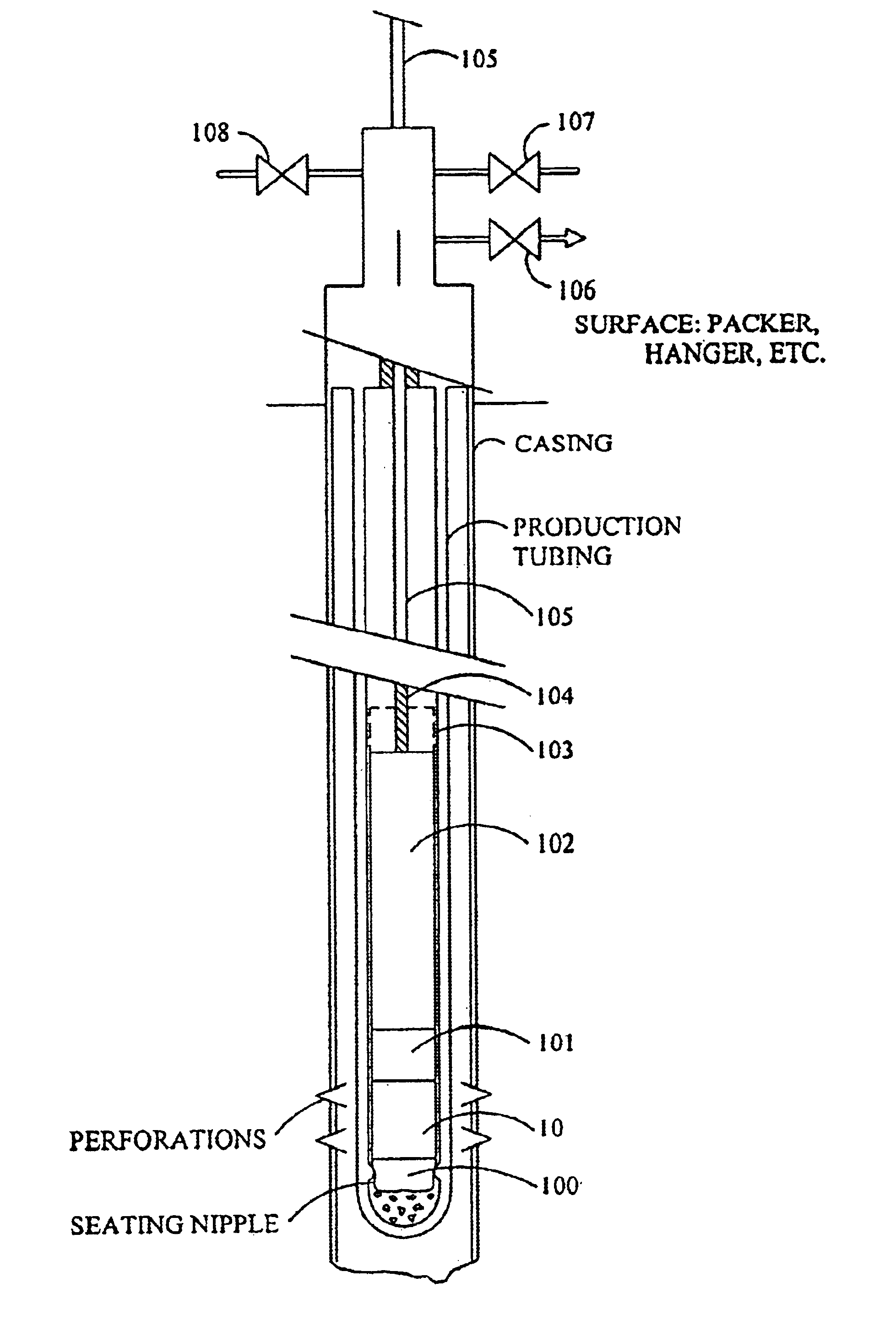
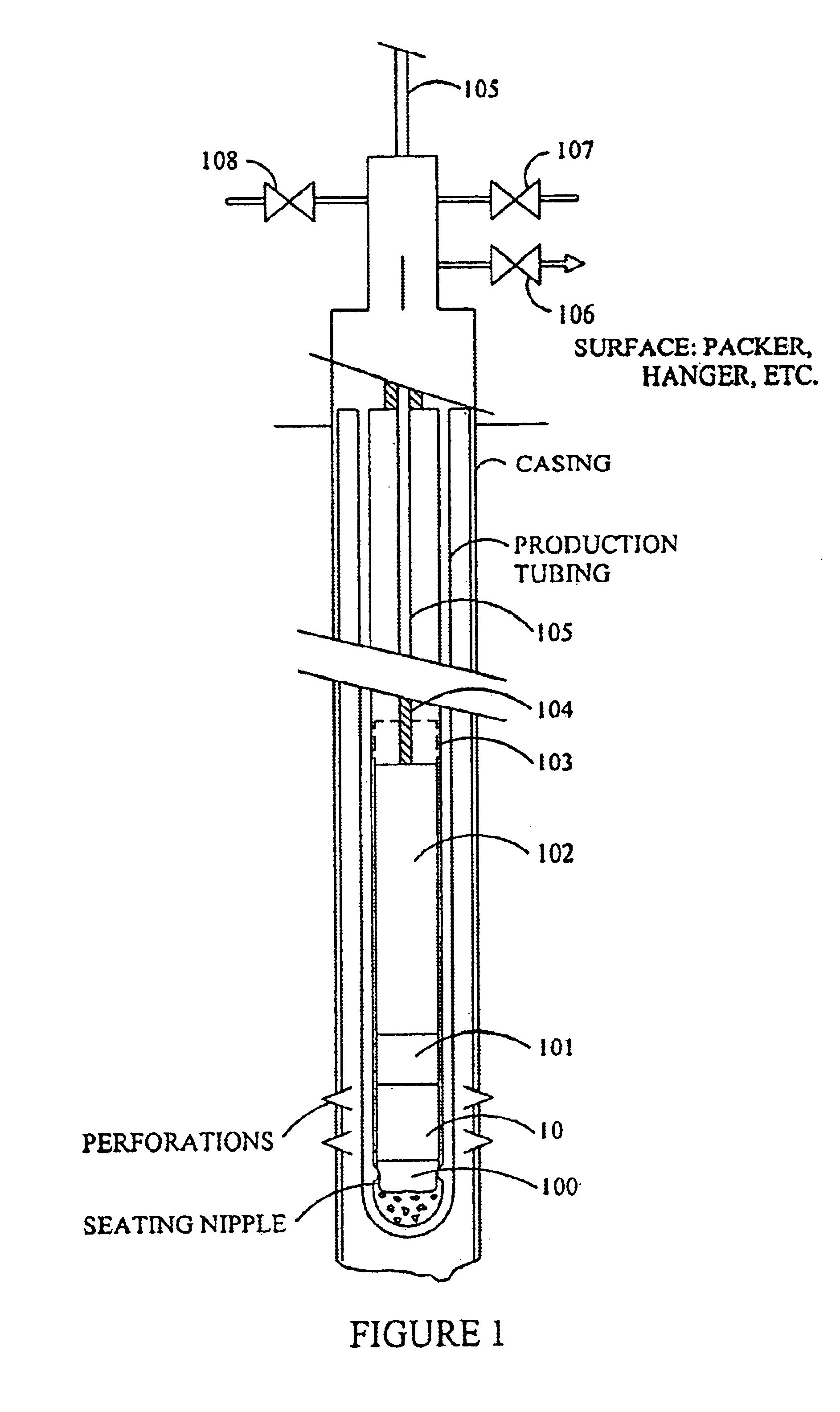
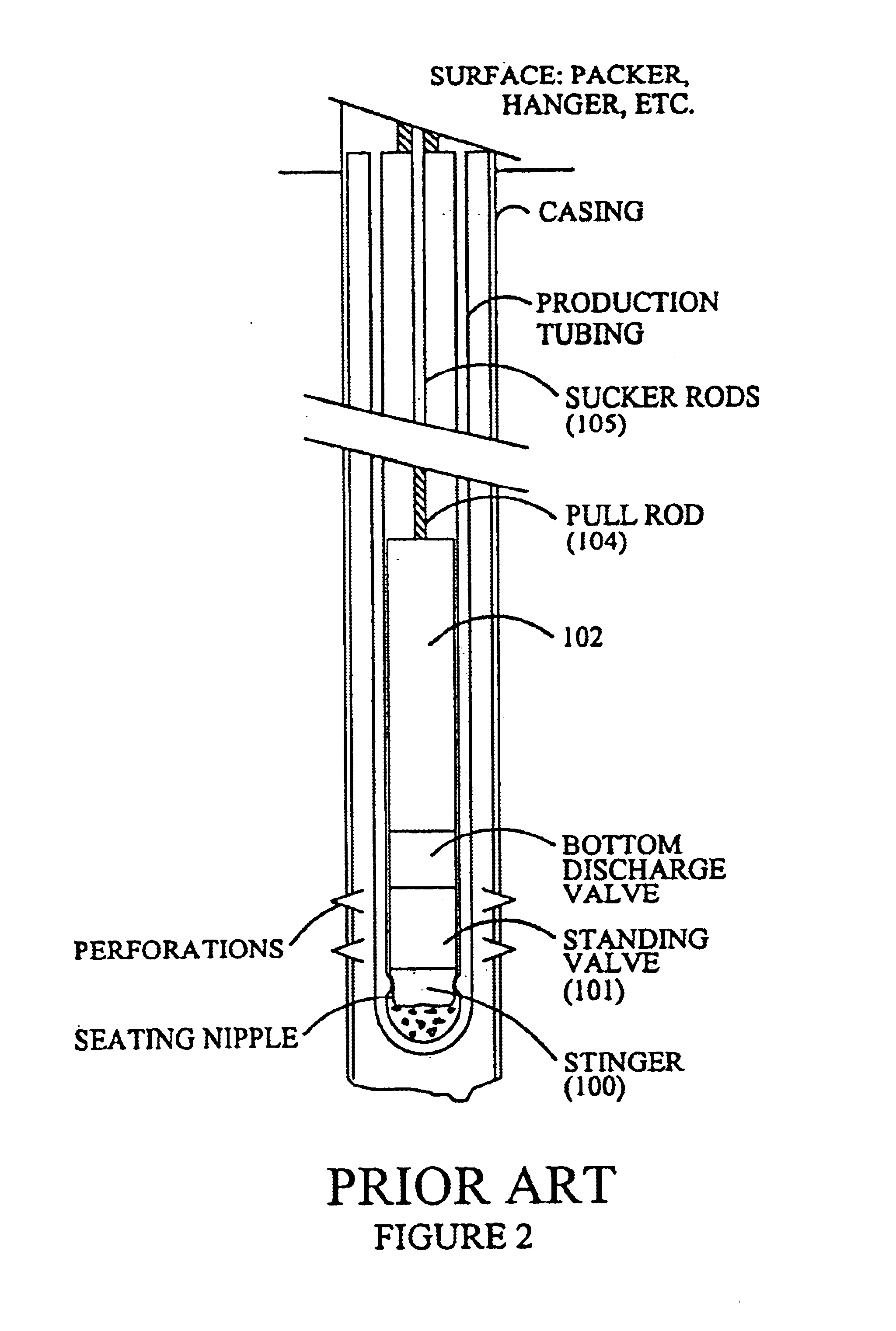
The device disclosed may be used in conjunction with tubing pump method, stationary pump barrel method, traveling barrel pump method, and other pumping methods that require a standing valve. The oil industry generally defines a standing valve as a valve that causes produced fluid to “stand” in the production tubing. When used in pumping operations, the standing valve in is a check valve (usually one or more ball and seat valves) that allows for the one-way passage of produced fluid from the formation to the surface.

The tubing pump method is probably the most common method of pumping. In the past, when using the tubing pump method, and prior to beginning pumping operations, a standing valve is dropped from the surface to seat into a standard seating nipple located at the bottom of the production tubing. This standing valve provides a means to apply pressure down the tubing to check its integrity and to check the seal the ball and seat, prior to inserting the tubing pump and beginning...


PUM


Abstract

A reciprocating pump vent-dump and methods of use for utilization in the hydrocarbon industry. The device is preferably used with barrel pumps although it may be used with tubing pumps. The device is positioned at the bottom of the wellbore immediately above the stinger and immediately below above the standing valve and comprises a sliding piston within an outer housing. The device may be opened pulling upwards on the pump drive mechanism thereby allowing fluid within the production tubing to drain back into the formation as long as the pump drive mechanism is held up. The device closes when the pump is returned to normal operation. The method of spotting chemicals requires a pre-measured quantity of chemicals at the surface which is sucked into the tubing string when the valve is opened followed by a pre-measured quantity of make-up fluid which is drawn into the well thereby placing the chemicals at the required point. The technique used for spotting chemicals may be used for flushing flower sand from the wellbore and the device may also be used to dump the hydrostatic head in the production tubing.

Description

BACKGROUND OF THE INVENTIONThe present invention relates generally to the oil and gas industry and in particular to oil well production utilizing reciprocating pumps.Oil wells are produced using a variety of methods ranging from self-production, where the formation pressure is high enough to cause the oil to flow up the wellbore, to various forms of artificial lift, where the formation pressure is insufficient and cannot lift the hydrocarbon fluid up the wellbore. The most common artificial form used in the oil industry is the reciprocating pump.The standard industry reciprocating pump consists of a prime mover that is positioned at the surface, and a pumping barrel that is positioned within the production tubing at or near the bottom of the wellbore. The wellbore is lined with steel pipe called casing.The production tubing is concentric within the casing and is the conduit through which produced fluids are sent to the surface. The area between the production tubing and the casing (...

Claims


Application Information

Patent Timeline
IPC IPC(8): E21B34/00E21B34/14E21B43/12
CPCE21B34/14E21B43/127Y10S166/902
Inventor VANN, ROY R.
Owner CHERRY SELECT S A P I DE
Why Eureka
Try Eureka