Rotating disc type grinding machine

A turntable, grinding machine technology, applied in the direction of grinding machine, grinding bed, grinding machine parts, etc., can solve the problem of high cost, and achieve the effect of reducing friction, reducing cost and preventing stuck.

Active Publication Date: 2020-08-11
浙江巍巍昆仑缝制设备有限公司
View PDF8 Cites 1 Cited by
  • Summary
  • Abstract
  • Description
  • Claims
  • Application Information

AI Technical Summary

Problems solved by technology

The rotary table grinder of the present invention has continuous action, fast clamping, automatic clamping, short time consumption, and accurate positioning, which ensures the processing quality of the workpiece. However, when this technology is used, each bending arm needs to be equipped with a motor. Bending work, higher cost

Method used


Image

  • Rotating disc type grinding machine
  • Rotating disc type grinding machine
  • Rotating disc type grinding machine

Examples


Embodiment 1

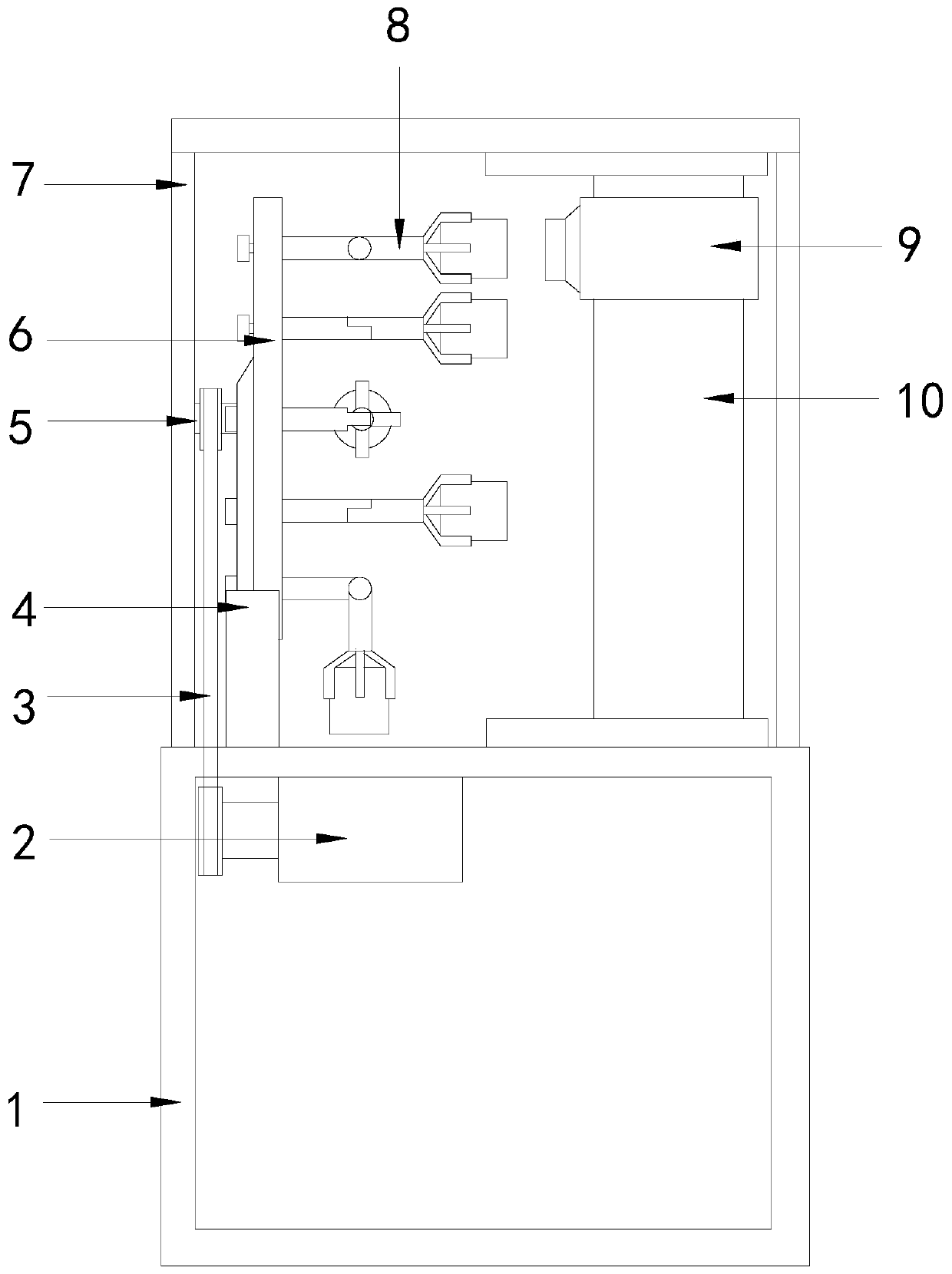
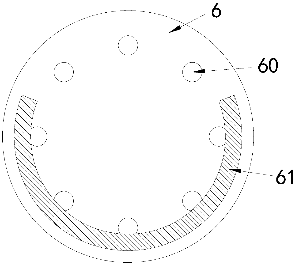
[0030] see Figure 1-7 , the present invention provides a technical solution for a turntable grinder: its structure includes a base 1, a motor 2, a belt drive 3, a support seat 4, a rotating shaft 5, a turntable 6, a bracket 7, a pole 8, a machine head 9, and a lifting guide rail 10 , the base 1 is connected with a bracket 7, the support base 4 is connected to the base 1, the turntable 6 is arranged on the support base 4, the middle of the support base 4 is connected with the rotating shaft 5, and the rotating shaft 5 passes through The belt transmission device 3 is connected with the motor 2, the motor 2 is installed in the base 1, the turntable 6 is connected with a pole 8, the pole 8 is connected with the mechanical claw, and the lifting guide rail 10 is arranged on the turntable 6 side, the machine head 9 is installed on the lifting guide rail 10, the turntable 6 is provided with a mounting hole 60, the back of the turntable 6 is provided with a retaining bar 61, and the p...

Embodiment 2

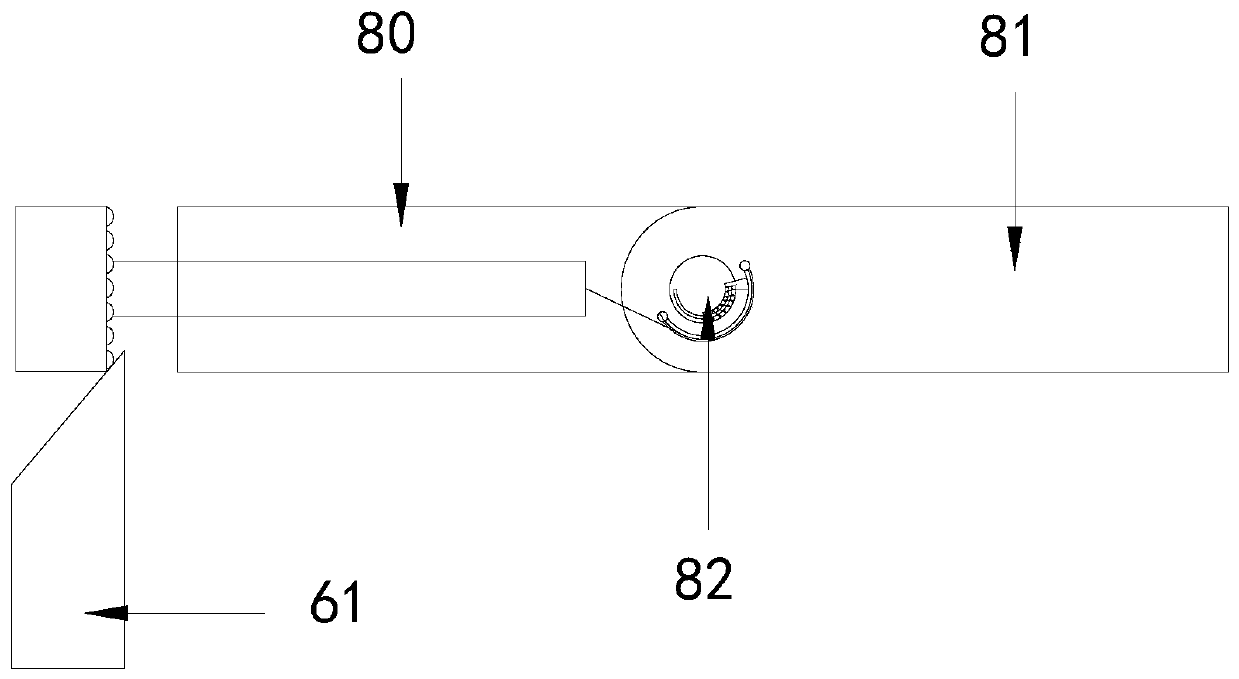
[0033] see Figure 1-8, the present invention provides a technical solution for a turntable grinder: its structure includes a base 1, a motor 2, a belt drive 3, a support seat 4, a rotating shaft 5, a turntable 6, a bracket 7, a pole 8, a machine head 9, and a lifting guide rail 10 , the base 1 is connected with a bracket 7, the support base 4 is connected to the base 1, the turntable 6 is arranged on the support base 4, the middle of the support base 4 is connected with the rotating shaft 5, and the rotating shaft 5 passes through The belt transmission device 3 is connected with the motor 2, the motor 2 is installed in the base 1, the turntable 6 is connected with a pole 8, the pole 8 is connected with the mechanical claw, and the lifting guide rail 10 is arranged on the turntable 6 side, the machine head 9 is installed on the lifting guide rail 10, the turntable 6 is provided with a mounting hole 60, the back of the turntable 6 is provided with a retaining bar 61, and the po...


PUM


Abstract

The invention discloses a rotating disc type grinding machine. The rotating disc type grinding machine structurally comprises a base, a motor, a belt transmission device, a supporting seat, a rotatingshaft, a rotating disc, a support, a supporting rod, a machine head and a lifting guide rail, wherein the support is connected to the base; the supporting seat is connected to the base; the rotatingdisc is arranged on the supporting seat; the middle of the supporting seat is connected with the rotating shaft; the rotating shaft is in transmission connection with the motor through the belt transmission device; the motor is mounted in the base; the supporting rod is connected to the rotating disc and connected with a mechanical claw; the lifting guide rail is arranged on the side face of the rotating disc; the machine head is mounted on the lifting guide rail; a mounting hole is formed in the rotating disc; a stop strip is arranged on the back face of the rotating disc; and the supportingrod is fixed in the mounting hole. The rotating disc type grinding machine has the beneficial effects that through cooperation of the stop strip and the supporting rod, a movable rod can be bent, andthe equipment cost can be reduced through bending and resetting actions conducted through mechanical transmission.

Description

technical field [0001] The invention relates to the field of grinders, in particular to a rotary disc grinder. Background technique [0002] Grinding machine is a kind of machine tool that uses abrasive tools to grind workpieces to obtain the required shape, size and precision machining surface. The processing action of grinding machine is grinding. The precise manufacture of mechanical parts depends on grinding work, which is also a part of precision machining. [0003] The existing patent No. is 201610801465.6 for a rotary disc grinder, which includes a frame; the frame includes a lower frame and a grinder frame; a grinding device and a rotary disc clamping device are arranged in the grinder frame; the grinding device includes Fixed frame, lower X-axis slide rail, upper X-axis slide rail, Y-axis slide rail and grinding wheel device; turntable clamping device includes turntable shell, clamping turntable, fixed arm, bending arm, jaws, transmission gear, turntable Support f...

Claims


Application Information

Patent Timeline
Patent Type & Authority Applications(China)
IPC IPC(8): B24B27/00B24B41/06B24B41/02B24B41/00
CPCB24B27/0069B24B41/005B24B41/02B24B41/06
Inventor 王康康
Owner 浙江巍巍昆仑缝制设备有限公司
Why Eureka
Try Eureka