Loading mechanism of storage device

a storage device and loading mechanism technology, applied in the direction of automatic cassette changing arrangement, data recording, instruments, etc., can solve the problems of large device cost, personnel expenses, management costs, and troublesome change of design of magnetic tape devices,

Inactive Publication Date: 2005-02-22
NEC CORP
View PDF14 Cites 10 Cited by
  • Summary
  • Abstract
  • Description
  • Claims
  • Application Information

AI Technical Summary

Benefits of technology

The present invention has been made in consideration of the above. It is accordingly an object of the present invention to provide a loading mechanism which can co

Problems solved by technology

Accordingly, it is quite troublesome to change the design of the magnetic tape device only in accordance with whether the cartridge holder is included.
Further, the stopper guide pushes up the upper stopper, thereby blocking the stopper function
If the cartridge is improperly loaded into the magazine, there will be made a space behind the cartridge because of the extending section of the cartridge.
However, the above-described structures are efficient for some usage, but not for various usage

Method used


Image

  • Loading mechanism of storage device
  • Loading mechanism of storage device
  • Loading mechanism of storage device

Examples


Embodiment Construction

A preferred embodiment of the present invention will now be explained with reference to the accompanying drawings.

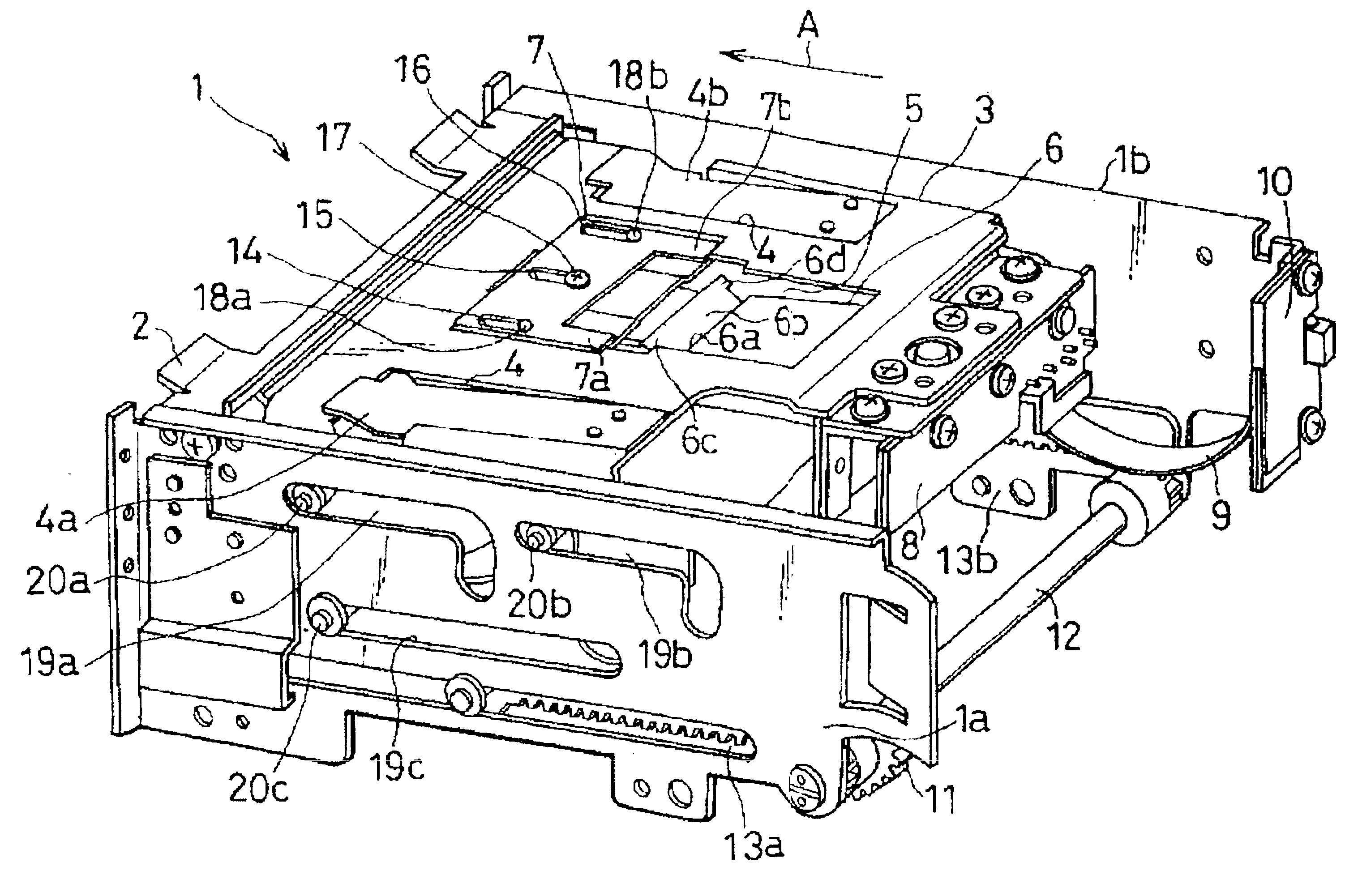
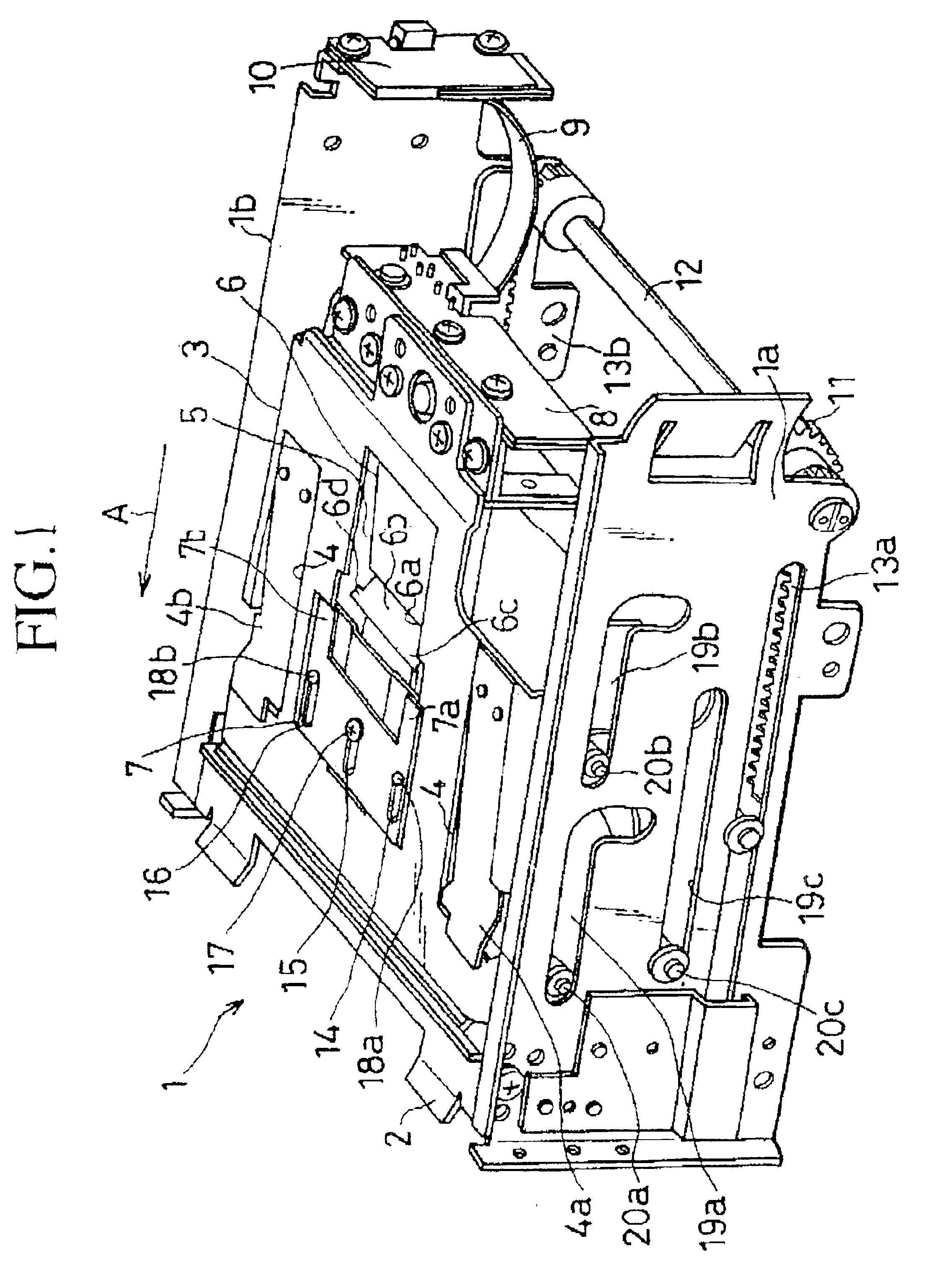
FIG. 1 is a perspective diagram showing a loading mechanism for loading a storage device. FIG. 1 shows a driving device included in a storage device, and shows also the structure of a loading mechanism for loading this driving device. In FIG. 1, for the sake of simple illustration of the loading mechanism, the casing of the loading mechanism is not shown. FIG. 1 shows also a state of the storage device, wherein a loading section of the loading mechanism which holds a cartridge in the storage device is operated.

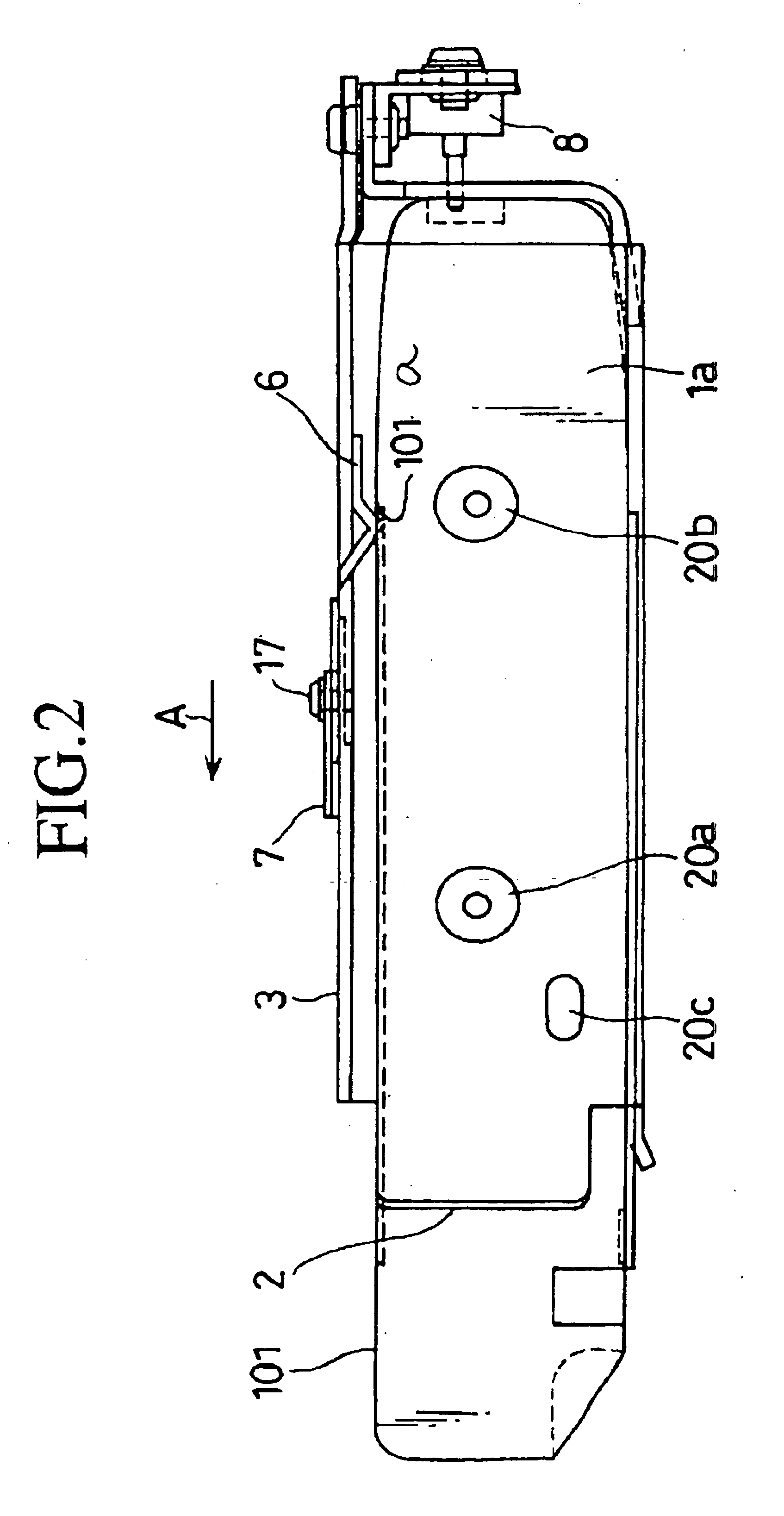
FIG. 2 shows a state of the storage device, wherein a cartridge is loaded into the loading mechanism.

FIG. 3 is an enlarged view showing the peripheral section of a stopper spring included in the loading section.

Explanations will now be made to the loading mechanism of the storage device, in the state wherein the loading section is operated.

As shown in FIG. 1, the l...


PUM


Abstract

A loading mechanism of a storage device includes a loader tray into which cartridge is loaded. A stopper spring is arranged on an opening of the loader tray. One side of the stopper spring is attached onto the loader tray, and the stopper spring is bent so as to include an engagement portion in a “V-like” shape. A pair of extending portions, extending toward the stopper spring, are formed on a side of a release plate. If the release plate is moved toward the stopper spring, the pair of extending portions move underneath an inclined portion of the stopper spring, so as to push up the engagement portion.

Description

BACKGROUND OF THE INVENTION1. Field of the InventionThe present invention relates to a loading mechanism of a storage device, and, more particularly, to a loading mechanism for loading / unloading a cartridge into / from a predetermined position of a storage device in order to write / read information onto / from a storage medium, such as a magnetic tape, etc. contained in the cartridge.2. Description of the Related ArtMany computer systems employ a magnetic tape device as a storage device. The magnetic tape device loads / unloads a cartridge including a magnetic tape into a loader tray of a loader section, thereby writing / reading information onto / from the magnetic tape. The loader section has a function for rewinding / unloading the magnetic tape after setting the cartridge contained in the loader tray into a predetermined position of the magnetic tape device. The magnetic tape device includes a detector, having various sensors, a magnetic head, and a driving section for moving a loader tray, ...

Claims


Application Information

Patent Timeline
IPC IPC(8): G11B15/675G11B15/68
CPCG11B15/67547
Inventor SUZUKI, TAKESHI
Owner NEC CORP
Why Eureka
Try Eureka