Method of marking ophhalmic lens by using laser radiation of femtosecond pulse width

a technology of ophhalmic lens and laser radiation, which is applied in the field of marking an ophhalmic lens, can solve the problems of insufficient safety, increased the number of process steps for marking the ophhalmic lens, and required additional steps, and achieves the effect of easy and clear reading or recognition

Inactive Publication Date: 2005-02-22
MENICON CO LTD
View PDF7 Cites 57 Cited by
  • Summary
  • Abstract
  • Description
  • Claims
  • Application Information

AI Technical Summary

Benefits of technology

The present invention was developed in the light of the background art described above. It is therefore an object of the present invention to provide a method of marking an ophthalmic lens, which method is capable of providing the ophthalmic lens with a marking that can be easily read or recognized with a high degree of visibility or clarity, without giving a feeling of discomfort to a lens user or causing problems such as contamination of the lens and reduction of the strength of the lens.
In a yet further preferred form of the present invention, the ophthalmic lens is formed of a polymer obtained from a polymerizable monomer which contains a methacrylic group or an acrylic group. Preferably, the ophthalmic lens is formed of a polymer obtained from methyl methacrylate. Where the marking is formed in the ophthalmic lens formed of the polymer described above, each whitened portion formed by irradiation of the lens with the laser radiation emits a fluorescent light by exposure to an excitation light. Accordingly, the marking can be easily and clearly read or recognized, with the fluorescent light emitted from the whitened portion formed in the ophthalmic lens.

Problems solved by technology

In the above-described printing method employed for marking the ophthalmic lens, however, the dye may get in the polymer of the lens, and may be contained in the ophthalmic lens, causing a problem of insufficient safety.
The printing method by which the identifying mark is directly formed using the ink or dye as described above inevitably increases the number of process steps for marking the ophthalmic lens and requires additional steps and devices such as a drying step and a device for drying the ink or dye after the printing step.
In addition, the ophthalmic lens needs to be handled frequently, undesirably resulting in a high defect or reject ratio of the ophthalmic lens.
Accordingly, the cost of manufacture of the ophthalmic lens is undesirably increased, causing a problem of poor economy.
In this case, the strength of the ophthalmic lens is reduced, and the ophthalmic lens tends to be easily broken.
Further, deposits (contaminants, stains) are likely to accumulate in the engraved or marked portions in the form of grooves or recesses, causing undesirable troubles such as irritation of the eye of the lens user.
In the latter method wherein the mark is formed on the lens surface corresponding to the recesses and protrusions of the mold, the mark in the form of protrusions formed on the front surface of the ophthalmic lens is in contact with the inner surface of the eyelid during wearing of the lens, so that the lens user may feel uncomfortable.
Even if the size of the mark and the amount of protrusion of the mark are made relatively small, it is impossible to completely get rid of the feeling of discomfort.

Method used


Image

  • Method of marking ophhalmic lens by using laser radiation of femtosecond pulse width
  • Method of marking ophhalmic lens by using laser radiation of femtosecond pulse width
  • Method of marking ophhalmic lens by using laser radiation of femtosecond pulse width

Examples


examples

There will be described some examples of the present invention to further clarify the present invention. It is to be understood, however, that the present invention is not limited to the details of the following examples.

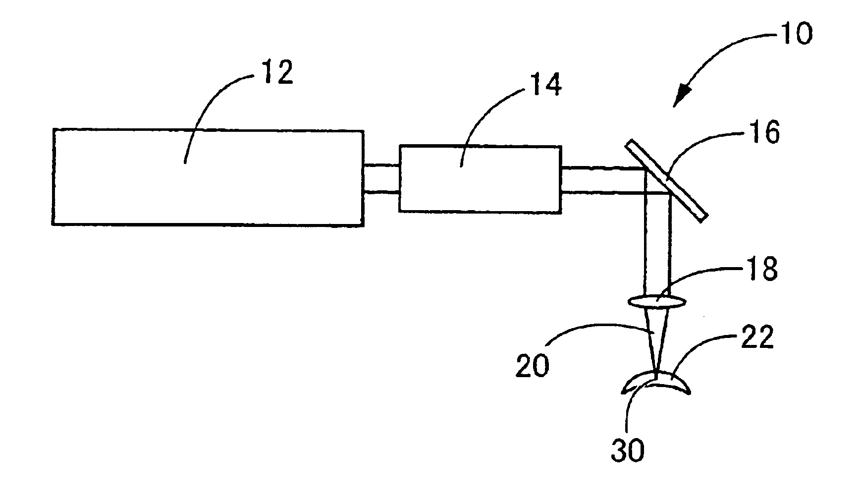
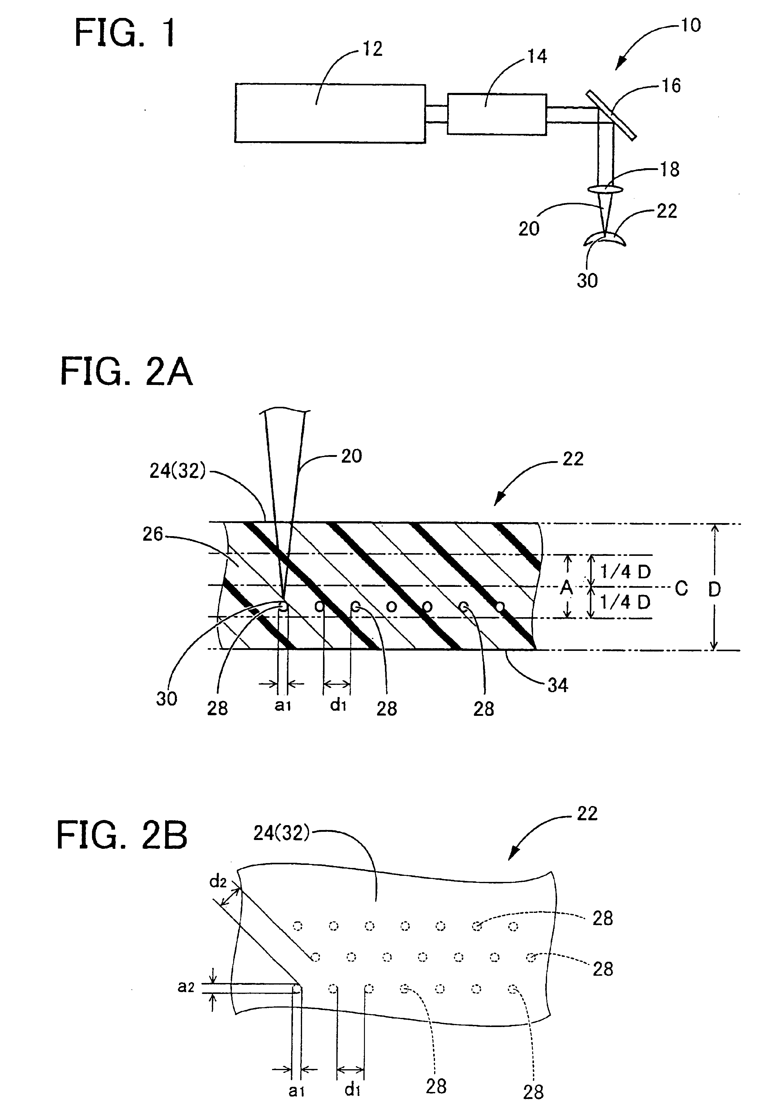
As the ophthalmic lens to be marked, there were prepared two plates (contact lenses) each having a thickness of 100 μm, by polymerizing a polymerizable composition containing methyl methacrylate and trimethyl silylpropyl methacrylate in a proportion of 50:50 by weight. One of the thus prepared two contact lenses was colored green by adding copper phthalocyanine in an amount of 0.005 wt. % to the polymerizable composition in the polymerization process. As the laser radiation source, a titanium sapphire laser was used.

Each contact lens was positioned on a three-axis piezoelectric actuator such that the laser radiation emitted from the laser radiation source was incident upon a desired portion of the contact lens and such that the laser radiation was focused at a prede...


PUM

PropertyMeasurementUnit
diameteraaaaaaaaaa
distanceaaaaaaaaaa
wavelength rangeaaaaaaaaaa

Abstract

A method of marking an ophthalmic lens, including a step of irradiating the ophthalmic lens formed of a resin material with a laser radiation of a femtosecond pulse width, such that the laser radiation is condensed at each of at least one predetermined spot within the ophthalmic lens, to form a whitened portion at the each of the at least one predetermined spot, for thereby providing the ophthalmic lens with a marking.

Description

This application is based on Japanese Patent Application No. 2001-281015 filed on Sep. 17, 2001, the contents of which are incorporated hereinto by reference.BACKGROUND OF THE INVENTION1. Field of the InventionThe present invention relates to a method of marking an ophthalmic lens such as a contact lens or an intraocular lens. More particularly, the present invention relates to a method of marking the ophthalmic lens by irradiating the ophthalmic lens with a laser radiation to thereby form, within the ophthalmic lens, a marking in the form of characters, figures, symbols, etc.2. Discussion of Related ArtConventionally, an ophthalmic lens such as a contact lens or an intraocular lens is provided with an identifying mark in the form of characters, figures, symbols, etc., principally for easy distinction between the front and back surfaces of the lens or between lenses for the left and right eyes, and / or indicating the specifications of the lens, for instance. For marking the ophthalmi...

Claims


Application Information

Patent Timeline
Patent Type & Authority Patents(United States)
IPC IPC(8): G02C7/02G02C7/04B23K26/00G02B1/04G02C7/00
CPCG02C7/021B41M5/267
Inventor NAKADA, KAZUHIKOSUZUKI, HIROAKIISHIHARA, KENICHIGOTOU, YUUJI
Owner MENICON CO LTD
Why Eureka
Try Eureka