Rotary actuator

a technology of rotary actuators and actuators, which is applied in the direction of synchronous motors, mechanical devices, gearing, etc., can solve the problems of reducing the axial dimensions of rotary actuators, and achieve the effect of high load capacity

Inactive Publication Date: 2005-02-22
NIPPON SOKEN +1
View PDF9 Cites 32 Cited by
  • Summary
  • Abstract
  • Description
  • Claims
  • Application Information

AI Technical Summary

Benefits of technology

The present invention has been devised with the above circumstances in mind, and an object of the present invention is to provide a compact rotary actuator having a high load capacity.

Problems solved by technology

Moreover, because the outer gear of the reduction gear meshes internally with the inner gear, the axial dimensions are made smaller, which in turn reduces the axial dimensions of the rotary actuator.

Method used


Image

  • Rotary actuator
  • Rotary actuator
  • Rotary actuator

Examples


Embodiment Construction

The following description of the preferred embodiments is merely exemplary in nature and is in no way intended to limit the invention, its application, or uses. Preferred embodiments of the present invention will be hereinafter described with reference to the accompanying drawings.

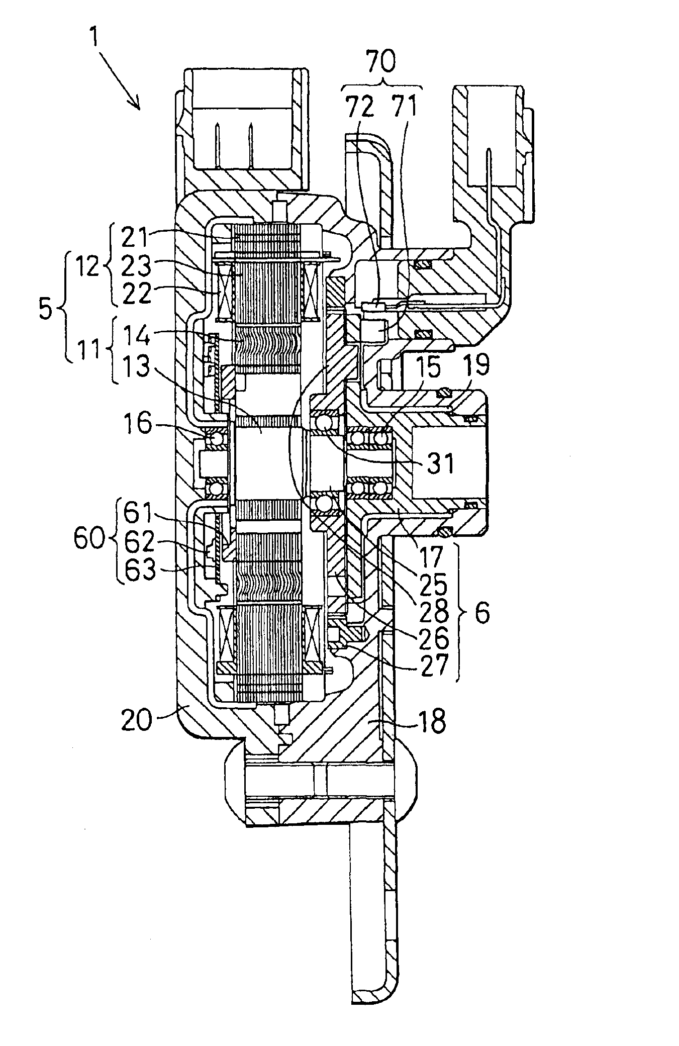
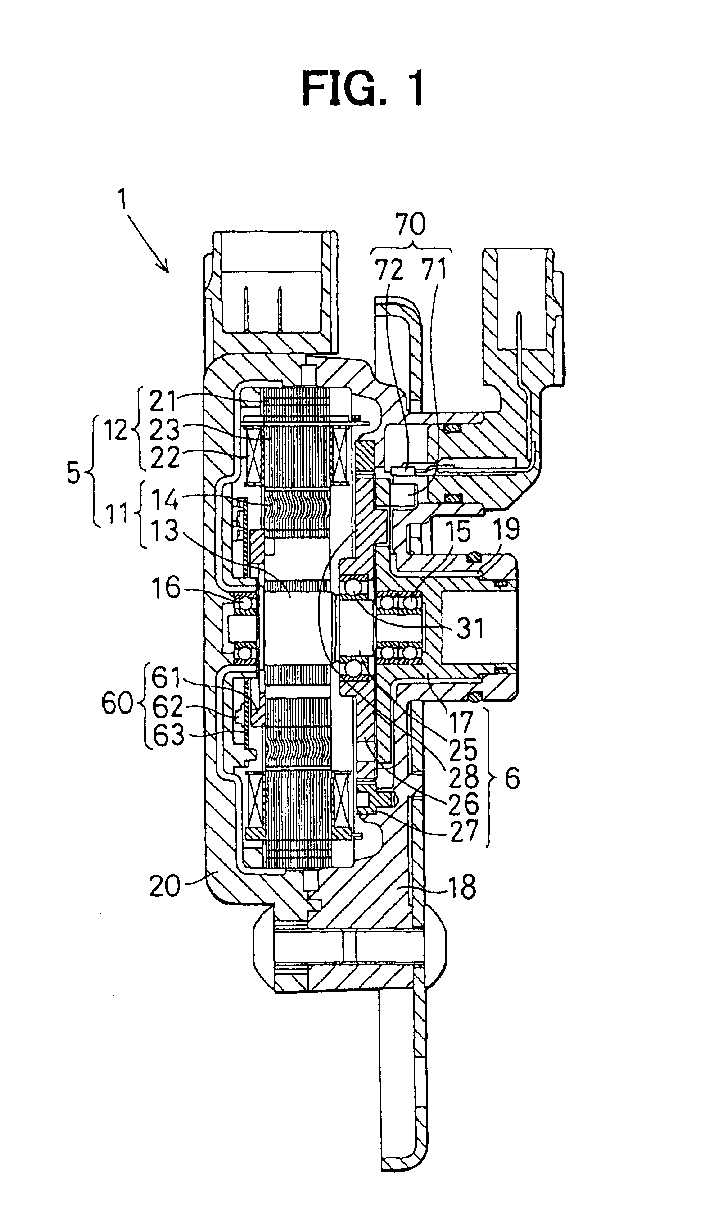
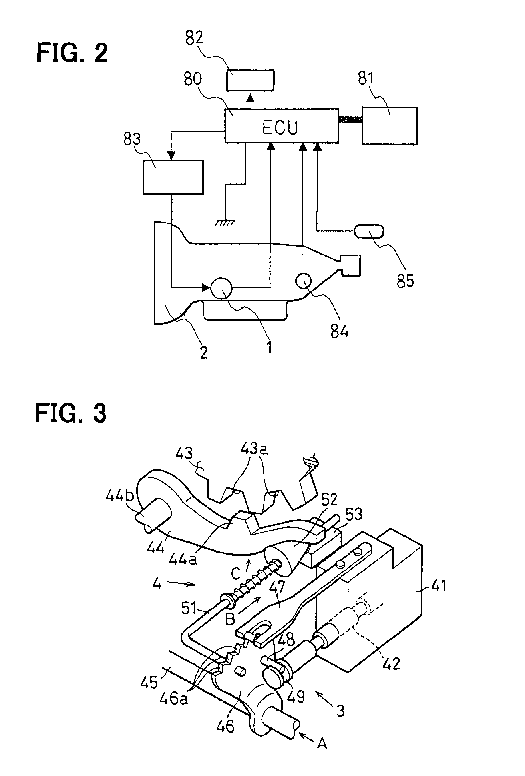
FIG. 1 shows one preferred embodiment of the invention adapted as a rotary actuator 1 incorporated in a shift range selector 3 including a parking lock 4 shown in FIG. 3 mounted in an automatic transmission 2 shown in FIG. 2 for a vehicle.

The rotary actuator 1 is used as a servo mechanism for driving the shift range selector 3 and is composed of a synchronous motor 5 (hereinafter “motor”) and an internally meshing planetary reduction gear 6 (hereinafter “reduction gear”). In the following description, the right side of FIG. 1 is known as the front side, and the left side is known as the rear side.

The motor 5 shown in FIG. 1 and FIG. 4 is a switched reluctance (SR) motor that does not use a permanent magnet...


PUM


Abstract

A rotary actuator has a synchronous motor and an internally meshing planetary reduction gear having a first shaft rotated by the synchronous motor, an outer gear mounted to said first shaft with an eccentric part so as to be eccentrically rotatable around said first shaft, an inner gear with which said outer gear meshes internally, and a second shaft connected to said outer gear with a transmission means that only transmits said outer gear rotation on its axis to the second shaft. The synchronous motor and the internally meshing planetary reduction gear are accommodated inside a housing, and the first shaft doubles as a rotor shaft of the synchronous motor. An incremental encoder provided along a rotary shaft of the synchronous motor detects the rotation angle of a rotor of the synchronous motor.

Description

CROSS REFERENCE TO RELATED APPLICATIONThis application is based upon, claims the benefit of priority of, and incorporates by reference, the contents of Japanese Patent Application No. 2002-212347 filed Jul. 22, 2002.BACKGROUND OF THE INVENTION1. Field of the InventionThe present invention relates to a rotary actuator for rotating a driven member, particularly suited for high load applications.2. Description of the Related ArtKnown techniques relating to rotary actuators include the following:1) Driving a driven member directly with the output shaft of a motor as shown, for example, in Japanese Patent Laid-Open Publication No. 2001-271925;2) Increasing the output torque of a motor with a worm and wheel set and driving a driven member with the output shaft of the worm reduction gear as shown, for example, in Japanese Patent Laid-Open Publication No. Hei 5-60217; and3) Increasing the output torque of a motor with a spur gear set and driving a driven member with the output shaft of the ...

Claims


Application Information

Patent Timeline
Patent Type & Authority Patents(United States)
IPC IPC(8): F16H1/32F16H61/28F16H61/32H02K29/06H02K7/116H02K29/08H02K5/22H02K19/02H02K11/00H02K19/10F16H63/00F16H63/48H02P25/08
CPCF16H61/32F16H63/3466H02K29/08H02K7/116H02K11/0021H02K11/0084H02K19/103H02K5/225F16H1/32F16H2061/326H02K11/215H02K11/38
Inventor HORI, MASASHIASA, HIRONORIKIMURA, KIYOSHIYOSHIYAMA, SHIGERU
Owner NIPPON SOKEN
Why Eureka
Try Eureka