Grounding mechanism retention feature

a grounding mechanism and retention feature technology, applied in the direction of coupling device connection, electrical apparatus construction details, coupling protective earth/shielding arrangement, etc., can solve the problems of thermal failure, uncontrollable springy leg positioning,

Active Publication Date: 2005-02-22
ORACLE INT CORP
View PDF8 Cites 17 Cited by
  • Summary
  • Abstract
  • Description
  • Claims
  • Application Information

AI Technical Summary

Benefits of technology

By engaging with a conductive aperture in the circuit board, secure mounting of the shielding assembly can be provided and an electrical connection for the shielding assembly can also be provided.

Problems solved by technology

However, with such an arrangement, the positioning of the springy legs is not well controlled and can be problematic, particularly in dense circuit board layouts.
Also, the shielding cage is not firmly located whereby poor thermal contact between the heatsink and components of the computer system can result, leading to potential thermal failure.

Method used


Image

  • Grounding mechanism retention feature
  • Grounding mechanism retention feature
  • Grounding mechanism retention feature

Examples


Embodiment Construction

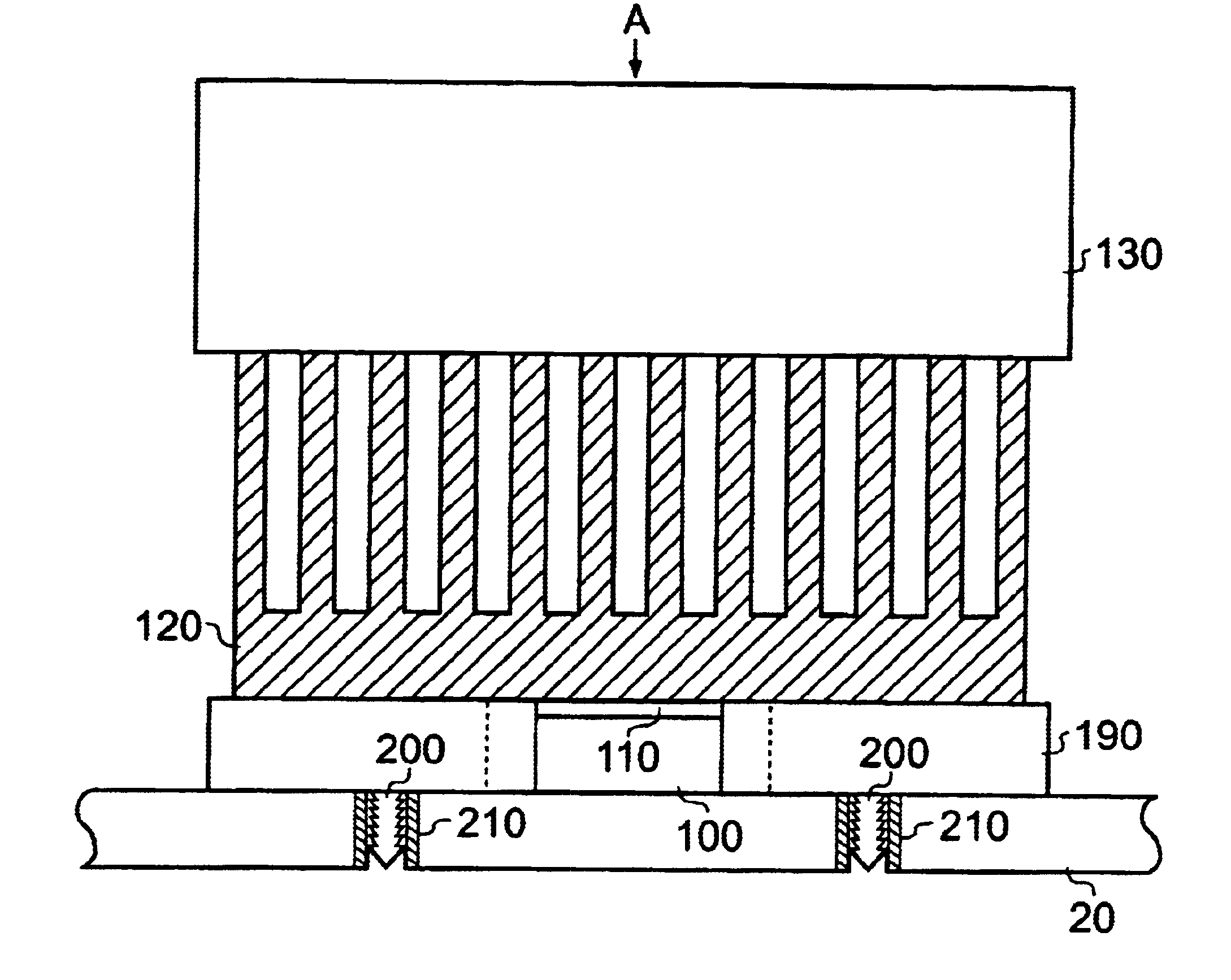
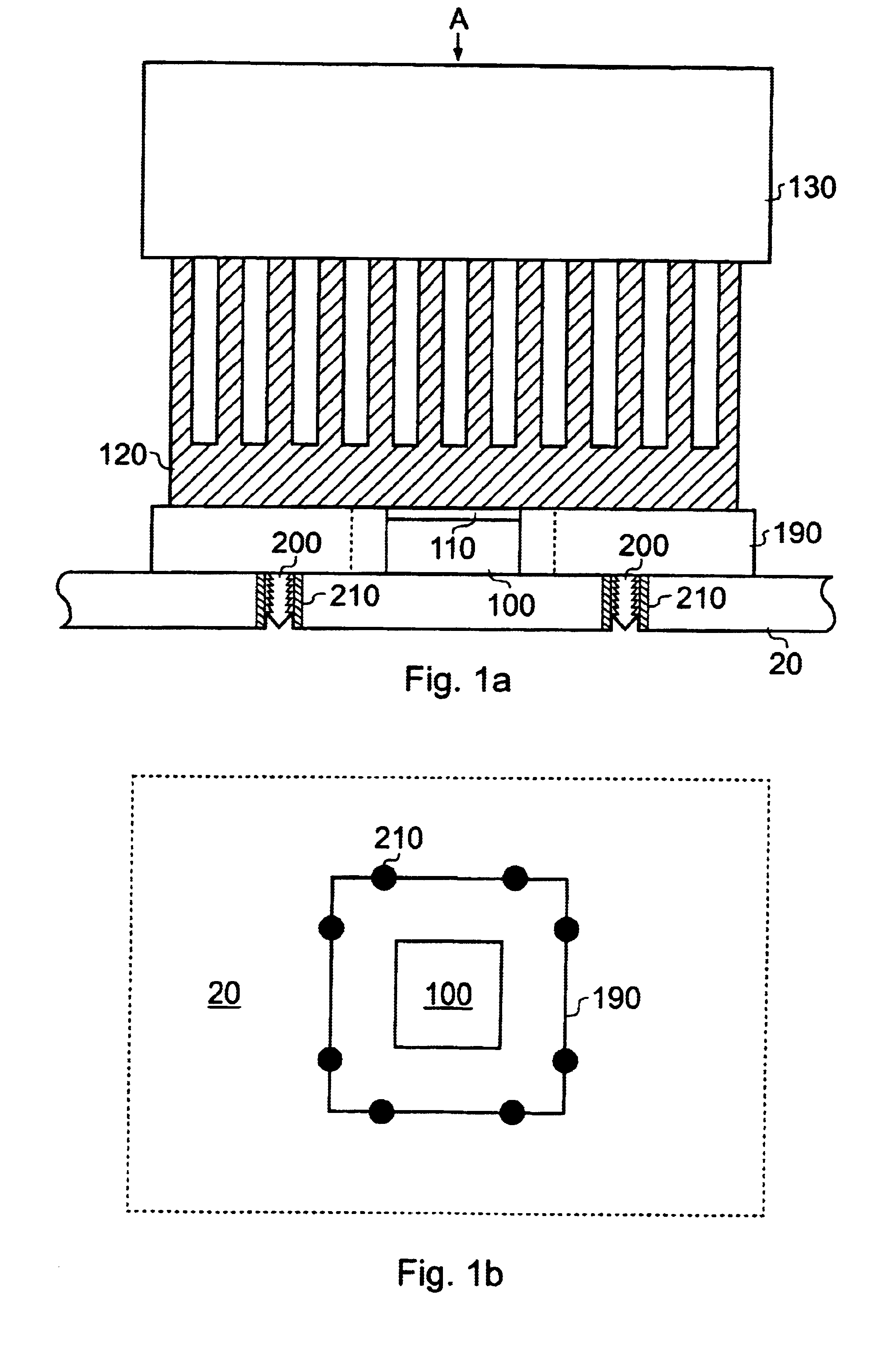
FIGS. 1a and 1b are schematic representations of an example of a shielding assembly. The shielding assembly provides EM shielding for a component (such as a processor chip or “CPU”100) mounted upon the surface of a circuit board such as a PCB 20. Although a CPU 100 is illustrated in this example, it will be appreciated the component could be any component that it is desired to shield. FIG. 1 also illustrates a heatsink 120 and fan unit 130 that may be provided in order to provide cooling for the CPU 100. The shielding assembly comprises a shielding cage 190 that surrounds the periphery of the CPU 100. In FIG. 1a, a portion of the shielding cage 190 indicated by the dashed lines has been cut away in order to show the configuration of the CPU 100 with respect to the remaining components of the assembly. Also shown is a thermal contact 110 that may be provided to improve thermal contact between the CPU 100 and the heatsink 120 (where one is provided). The thermal contact 110 may, for e...


PUM


Abstract

An electromagnetic (EM) shielding assembly includes an electrically conductive shielding portion and one or more electrically conductive protrusions for engaging with respective conductive apertures in a circuit board. The electrically conductive protrusions can be in electrical communication with the EM shielding portion. The protrusions can enable the EM shielding assembly to be attached to a circuit board in a computer system while also providing an electrical connection to logical ground. Further components, for example a heat sink that may be in electrical communication with the EM shielding portion, may thereby also be connected to logical ground.

Description

BACKGROUND OF THE INVENTIONThe present invention relates to electromagnetic (EM) shielding in computer systems. In particular, the invention relates to the physical attachment of an EM shielding cage to a circuit board and further to the electrical connection of an EM shielding cage to a desired voltage level.Shielding cages can be provided in computer systems for providing electromagnetic shielding for components of the computer system such as a microprocessor. Where the component to be shielded is mounted upon a circuit board in the computer system, the shielding cage can be mounted upon the circuit board. The shielding cage can also be electrically connected to a predetermined voltage level (for example an earth voltage) so as to facilitate effective shielding. This can be achieved by means of a springy leg on the shielding cage that can contact a grounded pad on the circuit board, when the shielding cage is sandwiched between a heatsink and the circuit board.However, with such a...

Claims


Application Information

Patent Timeline
Patent Type & Authority Patents(United States)
IPC IPC(8): H05K9/00H05K3/30
CPCH05K3/308H05K2201/10371H05K2201/10878H05K2201/10787H05K2201/1059
Inventor GARNETT, PAUL JEFFREYOSBORN, JAY KEVINBESTWICK, GRAHAM
Owner ORACLE INT CORP
Why Eureka
Try Eureka