Multi-frequency piezoelectric energy harvester

a piezoelectric energy harvester and multi-frequency technology, applied in piezoelectric/electrostrictive/magnetostrictive devices, piezoelectric/electrostriction/magnetostriction machines, electrical equipment, etc., to maximize the amount of energy each mems element generates

Inactive Publication Date: 2005-02-22
THE BOEING CO
View PDF21 Cites 353 Cited by
  • Summary
  • Abstract
  • Description
  • Claims
  • Application Information

AI Technical Summary

Benefits of technology

According to the principles of the present invention, large arrays of MEMS devices having weighted, cantilevered, piezoelectric beams in a bimorph configuration, oscillate and produce electrical current from vibrations of the surface to which they are attached. The piezoelectric power source of the present invention can be integrated in a variety of applications, including wireless sensor modules. The power devices of

Problems solved by technology

The sheath in one embodiment also provides a boundary limit, so that each piezobimorph

Method used


Image

  • Multi-frequency piezoelectric energy harvester
  • Multi-frequency piezoelectric energy harvester
  • Multi-frequency piezoelectric energy harvester

Examples


Embodiment Construction

The following description of the preferred embodiment(s) is merely exemplary in nature and is in no way intended to limit the invention, its application, or uses.

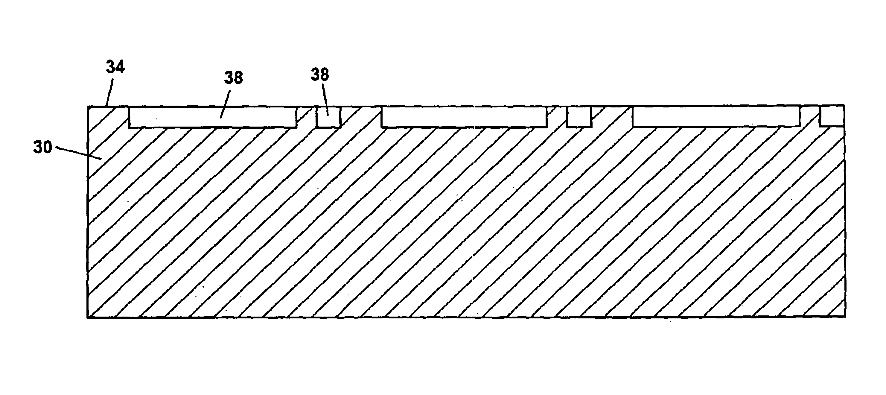
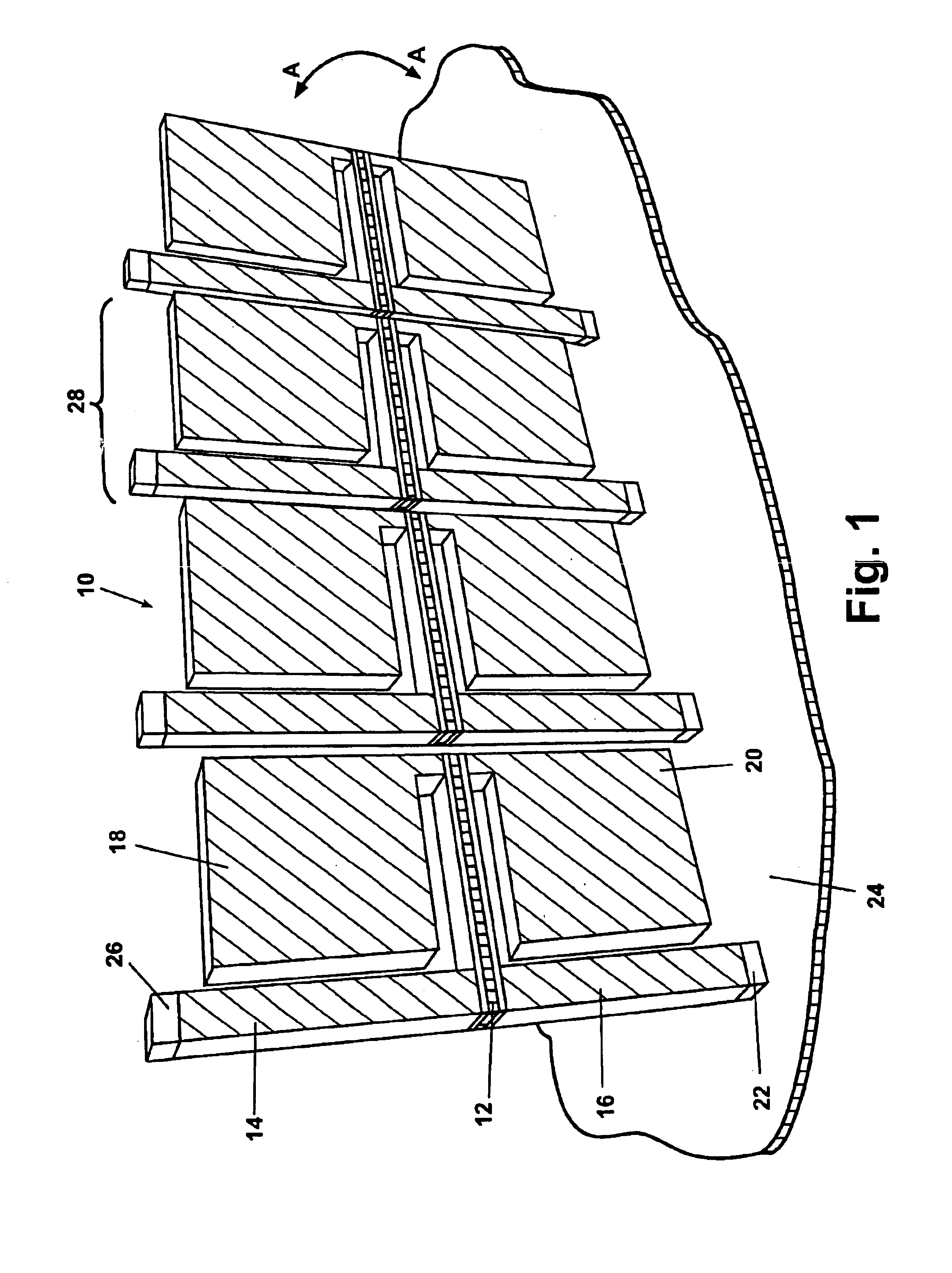
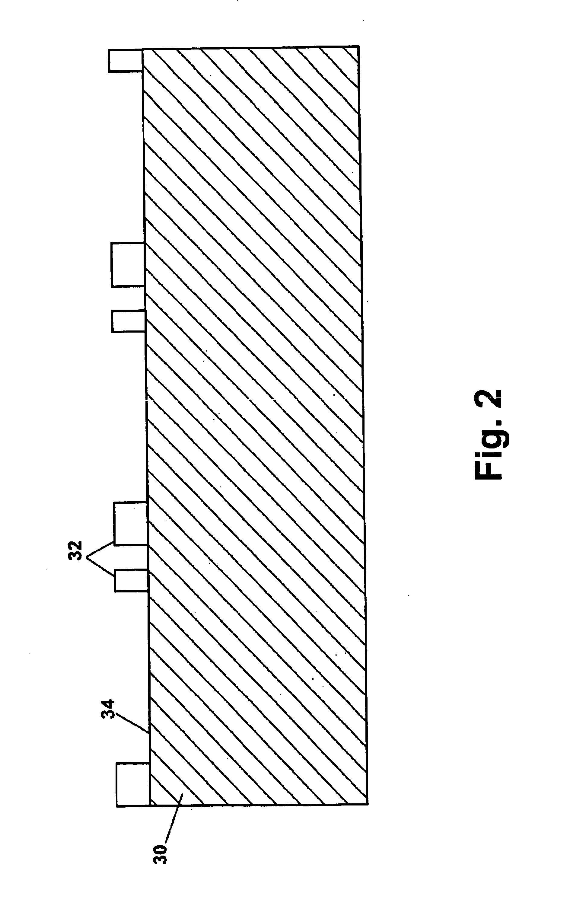
Referring to FIG. 1, a MEMS partial unit cell 10 is shown. Partial unit cell 10 comprises a plurality of piezoelectric cantilevered beams 12. At a fixed or support end of each of the piezoelectric cantilevered beams 12, an intermediate upper column 14 and an intermediate lower column 16 are provided. At a distal end of each piezoelectric cantilevered beam 12, an upper cantilevered mass 18 and a lower cantilevered mass 20 are provided. The upper and lower cantilevered masses 18 and 20, respectively, are provided to lower the resonant mode of the relatively short and stiff piezoelectric cantilevered beam 12.

When attached to a vibrating structure or item, the partial unit cell 10 will vibrate in response to the vibration source. The upper cantilevered mass 18 and the lower cantilevered mass 20 will deflect in the mass directio...


PUM


Abstract

A piezoelectric device connected to a vibration source converts vibration energy to electrical current. A plurality of pairs of oppositely polarized piezoelectric wafers deflect to produce an electrical current. Each pair of wafers are arranged back-to-back and electrically joined together. The plurality of pairs of wafers are each connected to a set of micro-machined parts. Each pair of wafers form a bimorph, configured as a cantilevered beam attached to a set of parts to form an element. Each cantilevered beam has a mass weighted first end and is fixedly attached to one or more flexible sheaths on a second end. A plurality of elements form a cell unit. A plurality of cell units form an array. The electrical current produced varies by the number of elements per cell unit, and/or with the number of cell units per array.

Description

FIELD OF THE INVENTIONThe present invention relates generally to piezoelectric devices which generate electrical energy by induced vibration and more specifically to an apparatus and method to utilize a thin, conformable sheet, having a plurality of piezobimorph cantilevered beams to produce electrical energy.BACKGROUND OF THE INVENTIONMoving objects or platforms generate vibration energy which is commonly steady in amplitude or that increases with age of the object or platform. All platforms suffer material degradation over time due to this continuous vibration, and for this reason system inspections are periodically performed or sensors are installed to monitor strain levels in such structures to help predict material failure. Common remotely addressable sensor devices require a power level in the milliwatt (mW) range. Batteries or other fuel sources can power such sensing devices. These power sources have drawbacks in that they require frequent maintenance or replacement, and in ...

Claims


Application Information

Patent Timeline
IPC IPC(8): H01L41/113H02N2/18
CPCH01L41/1136H10N30/306
Inventor MALKIN, MATTHEW C.DAVIS, CHRISTOPHER L.
Owner THE BOEING CO
Why Eureka
Try Eureka