Liquid crystal display having a concave substrate and manufacturing method thereof

a liquid crystal display and concave substrate technology, applied in non-linear optics, instruments, optics, etc., can solve the problems of defective liquid crystal display, voids observed in the lcd cell, and voids or gravity mura problems, and achieve the effect of a larger lc dispensing process window

Inactive Publication Date: 2005-02-22
INNOLUX CORP
View PDF3 Cites 5 Cited by
  • Summary
  • Abstract
  • Description
  • Claims
  • Application Information

AI Technical Summary

Benefits of technology

Therefore, it is an object of the present invention to provide a method for manufacturing a liquid crystal display with liquid crystal (LC) mat...

Problems solved by technology

However, a problem can arise in that the quantity of the LC material in the LCD cell can become excessive or insufficient because of the dispensing accuracy of the dispenser and variation of the cell gap defined between ...

Method used


Image

  • Liquid crystal display having a concave substrate and manufacturing method thereof
  • Liquid crystal display having a concave substrate and manufacturing method thereof
  • Liquid crystal display having a concave substrate and manufacturing method thereof

Examples


Embodiment Construction

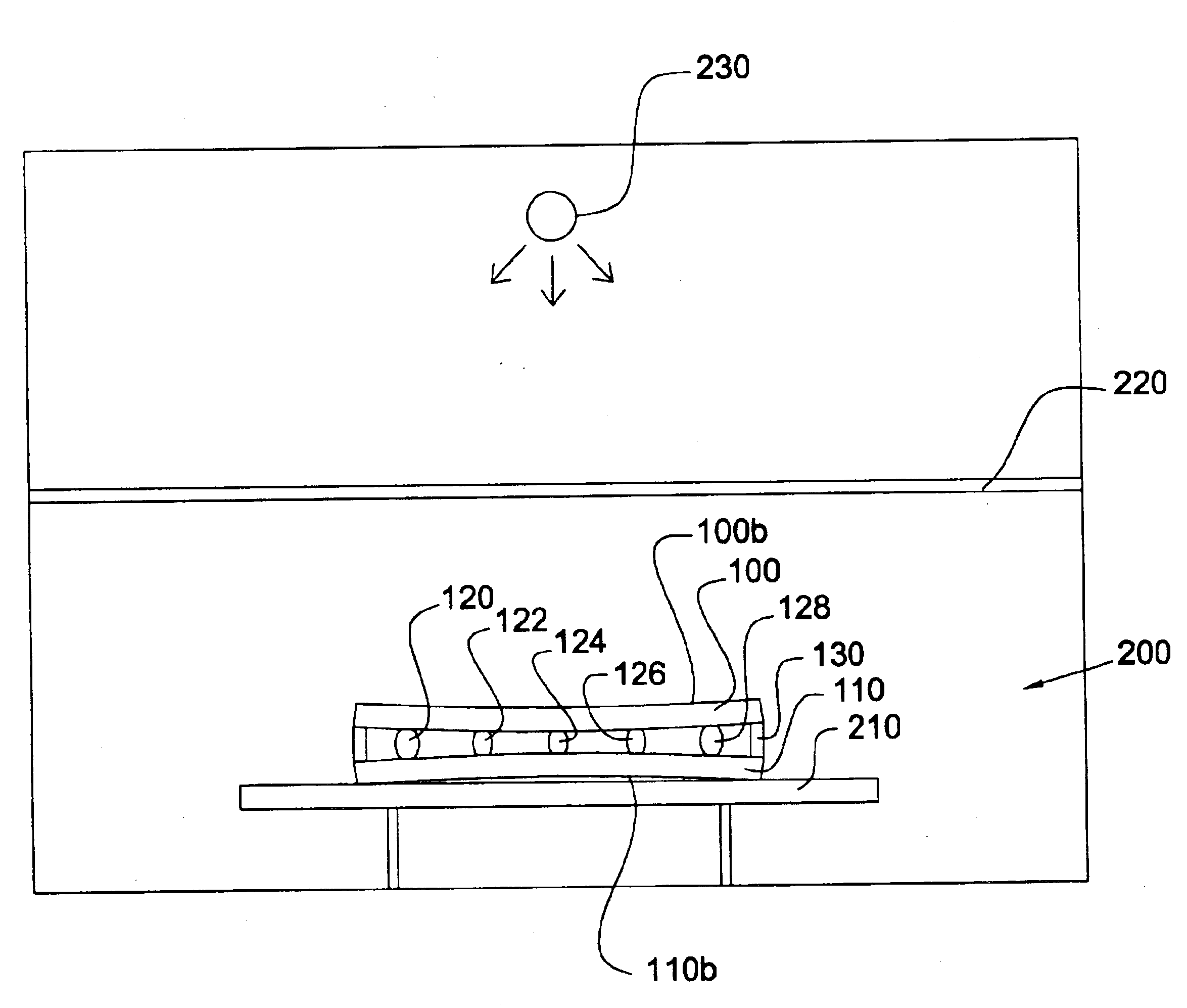
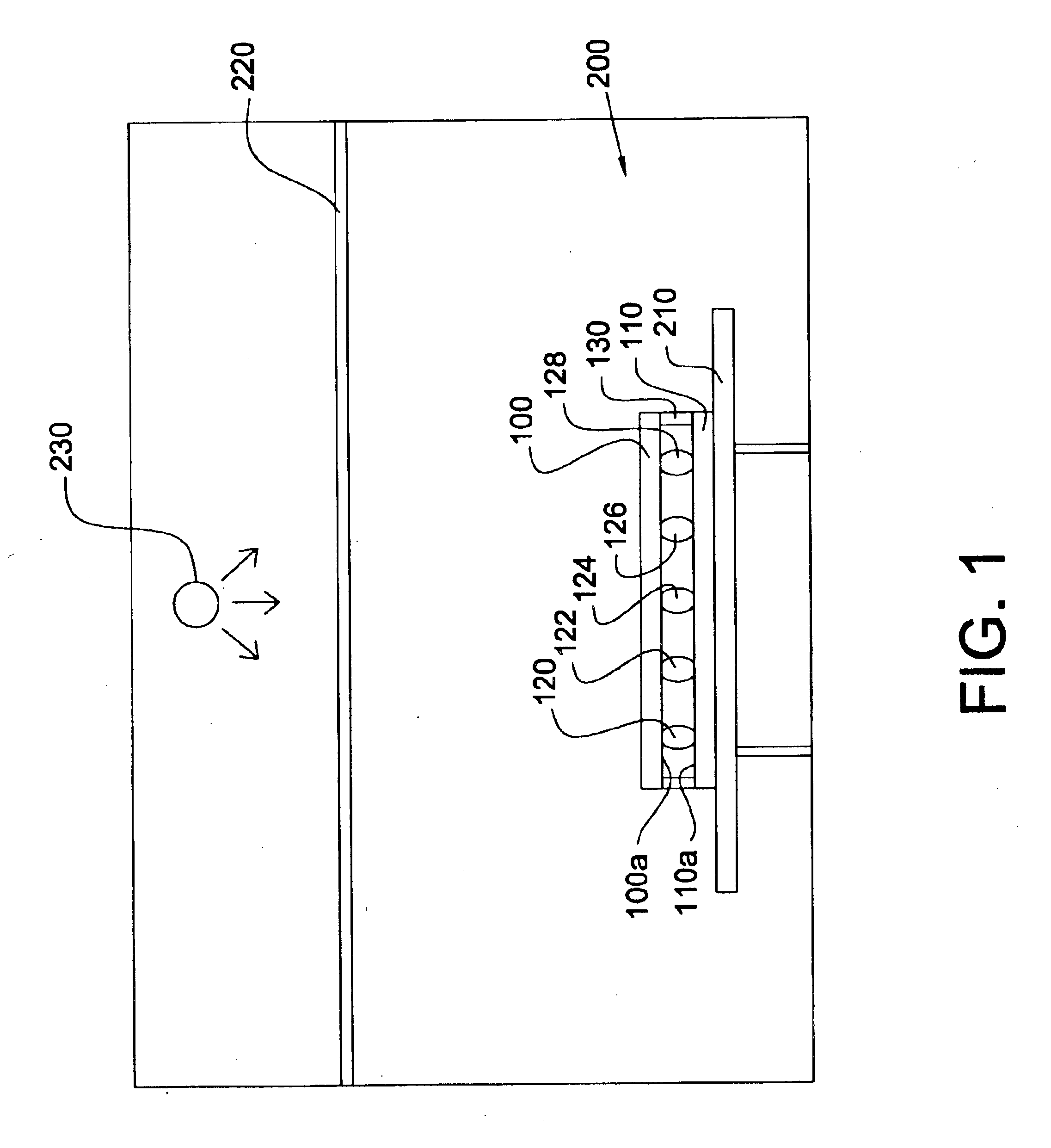
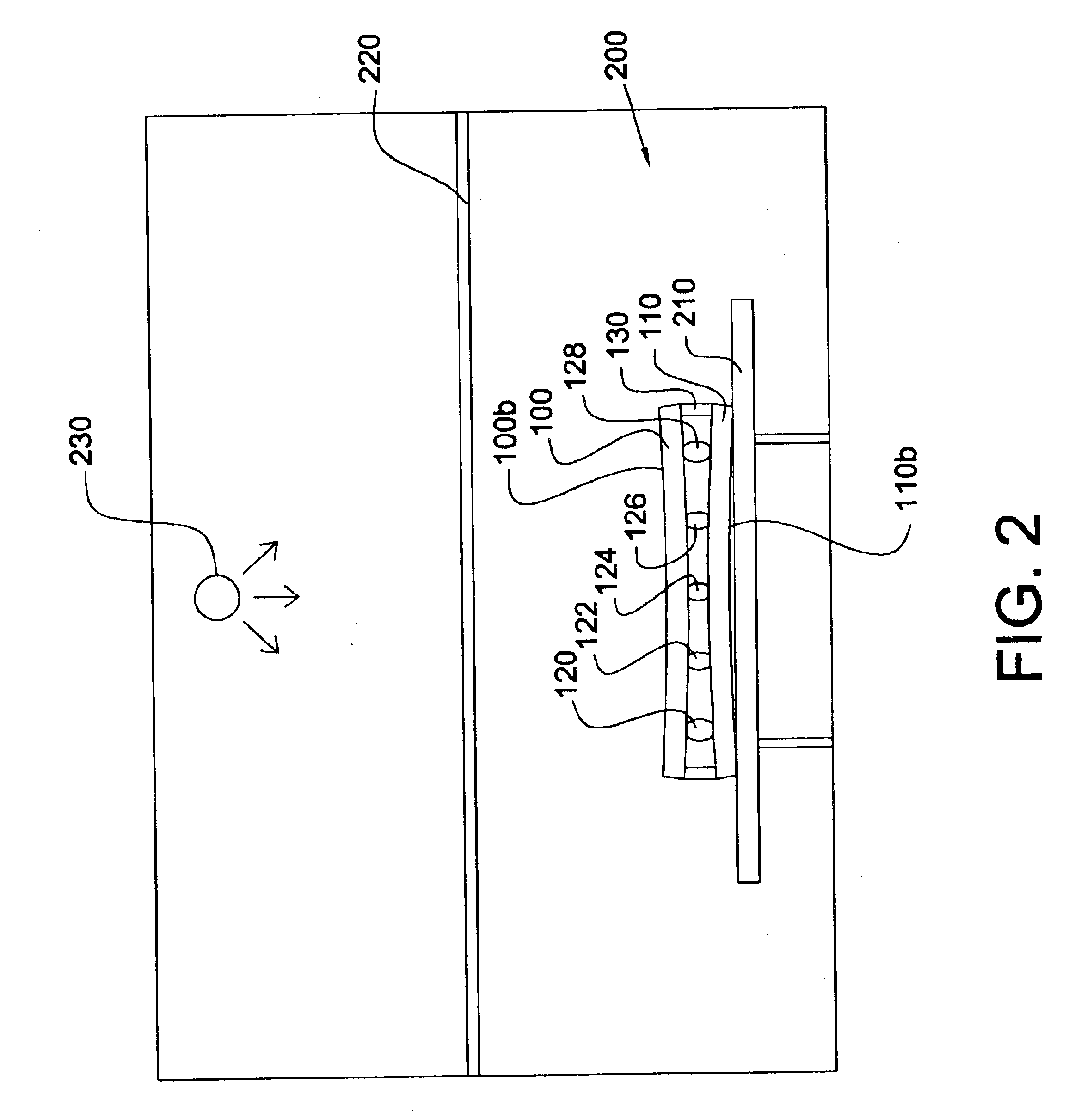
The present invention provides a method for manufacturing a liquid crystal display with liquid crystal (LC) material sealed between two substrates using a one drop fill (ODF) process. One substrate is typically provided with a plurality of scan bus lines formed parallel to one another, a plurality of data bus lines formed parallel to one another vertically to the scan bus lines, and TFTs and pixel electrodes formed like a matrix at intersections between the scan bus lines and data bus lines. The other substrate is typically provided with a light-shielding matrix (such as black matrix BM), a plurality of color filters for displaying colors and a transparent electrode such as an ITO electrode as a common electrode. As illustrated in FIG. 1, numerals 100 and 110 denote respective substrates with the bus lines, TFTs, the electrodes, and BM being omitted from the drawing for simplicity. Spacers are formed between the substrates 100 and 110 in order to maintain a cell gap between the subs...


PUM


Abstract

A liquid crystal display and a method for manufacturing the liquid crystal display is disclosed. The method includes the steps of: (a) applying an adhesive onto at least one of a pair of substrates; (b) dispensing a liquid crystal material to at least one of the pair of substrates; (c) superposing one of the pair of substrates upon the other substrate; and (d) conducting a curing process of the adhesive in an air pressure greater than atmospheric pressure such that one of the substrates is concave toward the other substrate in the finished liquid crystal display.

Description

BACKGROUND OF THE INVENTION1. Field of the InventionThe present invention relates to a liquid crystal display (LCD) and, more particularly, to a liquid crystal display with liquid crystal (LC) material sealed between two substrates using a one drop fill (ODF) process.2. Description of the Related ArtLiquid crystal display typically comprises two glass substrates oppositely positioned and a liquid crystal layer interposed therebetween. Specifically, the glass substrates are assembled by the following steps. First, an adhesive seal material is applied, usually by either silkscreening or screen printing. An opening is left in the seal for liquid crystal (LC) material injection in the subsequent process. After the adhesive is applied, spacers are provided on one of the substrates to maintain a precise cell gap (between 3-10 micrometers) between the two substrates. Typically, the spacers are formed by spraying glass or plastic beads on one of the substrates or by using resin to fabricate...

Claims


Application Information

Patent Timeline
IPC IPC(8): G02F1/13G02F1/1339
CPCG02F1/1339
Inventor WANG, JYH CHAUPAN, CHENG CHETING, CHIN LUNG
Owner INNOLUX CORP
Why Eureka
Try Eureka