Random microlens array for optical beam shaping and homogenization

a random microlens array and beam shaping technology, applied in the field of optical devices, can solve the problems of limiting the usefulness of methods, providing very limited beam shaping capabilities, and limiting the usefulness of holographic components to anything other than a gaussian spread of ligh

Inactive Publication Date: 2005-02-22
CORNING INC
View PDF7 Cites 114 Cited by
  • Summary
  • Abstract
  • Description
  • Claims
  • Application Information

AI Technical Summary

Problems solved by technology

Such beam shapers are inexpensive and easy to fabricate but provide very limited beam-shaping capabilities.
Other intensity profiles could in principle be obtained; but the holographic method of fabrication assumes a device with the desired intensity profile already exists, which limits the usefulness of the method.
These drawbacks limit the usefulness of holographic components to anything other than a Gaussian spread of light.
Problems with diffractive elements arise when large divergence angles are required, since diffractive elements achieve light spreading by reducing surface feature sizes (small features lead to large scattering angles).
As divergence angles increase, it becomes harder to fabricate diffractive elements, which are typically limited to angles below ±20 degrees.
Diffractive elements can be designed to operate at discrete wavelength values; but for broadband operations, such devices offer poor performance, with the zero order being the main source of degradation.
Aspheric lenses have also been used for beam flattening; but aspheric lenses present difficulties relating to fabrication, alignment, limited depth of field, and sensitivity to input beam variations.
Regular microlens arrays have been previously used for near-field homogenization, but these arrays produce strong diffraction patterns away from the array as well as image artifacts such as moire effects in screen applications.
Regular microlens arrays have also been used for illumination purposes but provide limited spatial shaping (polygonal energy distribution) and limited intensity control (spherical or aspheric lens profiles on a regular array) away from the array.
Except for diffractive elements, prior methods have been unable to provide beam-shaping capabilities that include such multiply-connected scatter patterns.

Method used


Image

  • Random microlens array for optical beam shaping and homogenization
  • Random microlens array for optical beam shaping and homogenization
  • Random microlens array for optical beam shaping and homogenization

Examples


Embodiment Construction

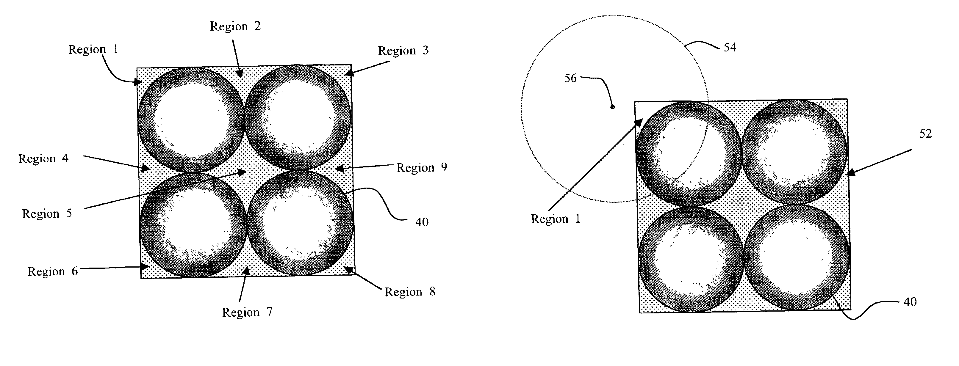
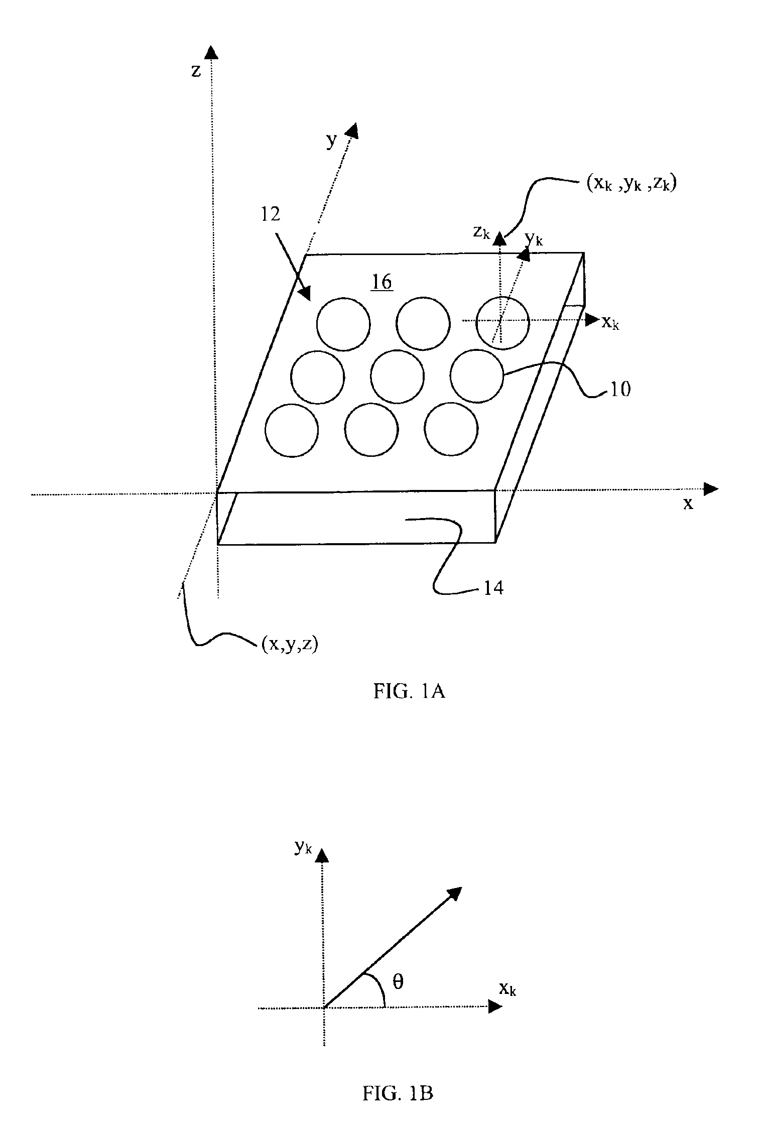
An embodiment of the invention referenced by FIGS. 1A and 1B relies on randomized microlenses 10 arranged in an array 12 on a substrate 14 to provide beam shaping and homogenization of input illumination. The substrate 14 upon which microlenses 10 are fabricated can be made from a variety of transmissive materials, including glass and plastic, that are capable of supporting or fabricating the microlenses 10. A surface 16 of the substrate 14 in which the microlenses 10 are formed can be divided into a number N of sections, where each section has identified with it a microlens structure, defined by particular values of a set of parameters. The microlenses 10 within each of the sections N of the substrate surface 16 can be defined by variables including radii of curvature, conic constants, and aspheric coefficients—all of a sag function mathematically representing the sag profile. The perimeter of an individual section N can assume any form such as a square, a rectangle, a hexagon, a p...


PUM


Abstract

Microlens arrays are defined with microlens elements that differ from each other in accordance with a probability distribution for shaping an optical beam having a prescribed intensity profile within a desired far-field scatter pattern. The differences include random variations in a sag profile corresponding to a surface shape of the microlenses, a boundary profile corresponding to a boundary of the microlenses, and a spatial distribution corresponding to the relative position of the microlenses within the array. The sag profile variations can be used to homogenize an intensity profile of the optical beam. The boundary profile variations within an irregular spatial distribution can be used to apply the prescribed intensity profile of the optical beam within the desired scatter pattern.

Description

TECHNICAL FIELDThe invention relates to optical devices based on microlens arrays that are capable of modifying or shaping intensity functions of input illumination into distinct intensity functions observed a distance away from the devices. The capabilities for modifying intensity functions include homogenization by reducing strong variations in the scattered intensity distribution. Applications of such microlens arrays include diffusers, screens, homogenizers, and beam shapers.BACKGROUNDBeam shaping refers to the transformation of the intensity profile of an initial input beam into a distinct profile a distance away from the beam-shaping devices. Often, beam shaping is desired in such a form that it deviates considerably from the natural shaping provided by free propagation alone (i.e., diffraction). Consequently, it often becomes necessary to employ beam-shaping devices to modify the nature of the propagating beam and thereby provide the desired shaping function.A simple form of ...

Claims


Application Information

Patent Timeline
Patent Type & Authority Patents(United States)
IPC IPC(8): G02B27/09G02B3/00G02B27/00
CPCG02B3/0043G02B3/005G02B27/0961G02B27/09G02B27/0927G02B3/0056G02B3/0068G02B1/041
Inventor SALES, TASSO R. M.
Owner CORNING INC
Why Eureka
Try Eureka