
Accurate distance measurement using RF techniques

a distance measurement and accurate technology, applied in the field of system and method for measuring the distance between two objects, can solve the problems of inability to directly measure the distance between two wireless devices, inconvenient, inconvenient, etc., and achieve the effect of accurately measuring distan

Inactive Publication Date: 2005-02-22
AEROSCOUT
View PDF34 Cites 98 Cited by
  • Summary
  • Abstract
  • Description
  • Claims
  • Application Information

AI Technical Summary

Benefits of technology

The present invention has been made in view of the above circumstances and has an object to provide a system and method for accurately measuring distance using RF techniques.

Problems solved by technology

These wireless devices are currently used for relatively limited purposes, such as making telephone calls, when they are capable of doing much more.
In many cases, it may be undesirable to measure the distance between two wireless devices directly.
Direct distance measurement may be impossible, impractical, intrusive, or simply inconvenient.
Moreover, because one or more wireless devices may be moved, the distance between devices will not be fixed indefinitely and re-calculation may be needed.
Radar as well as ultra sonic systems are bulky, complex, and consume significant amounts of power.
New ultra wide band techniques are currently not approved by the authorities.
Some less expensive systems offer solutions based on field strength measurements with the tradeoffs of reduced reliability and high environmental dependency.

Method used


Image

  • Accurate distance measurement using RF techniques
  • Accurate distance measurement using RF techniques
  • Accurate distance measurement using RF techniques

Examples


Embodiment Construction

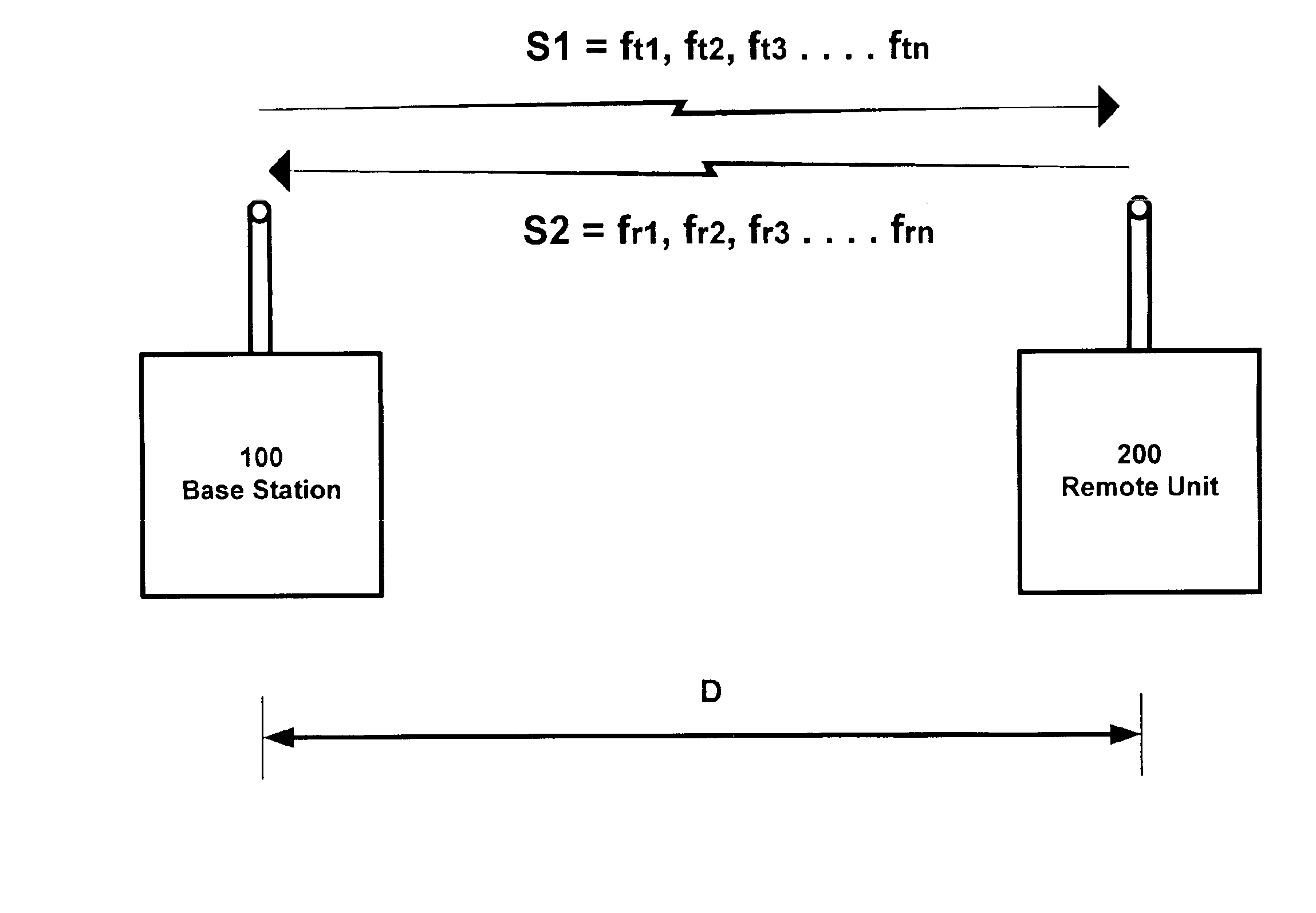
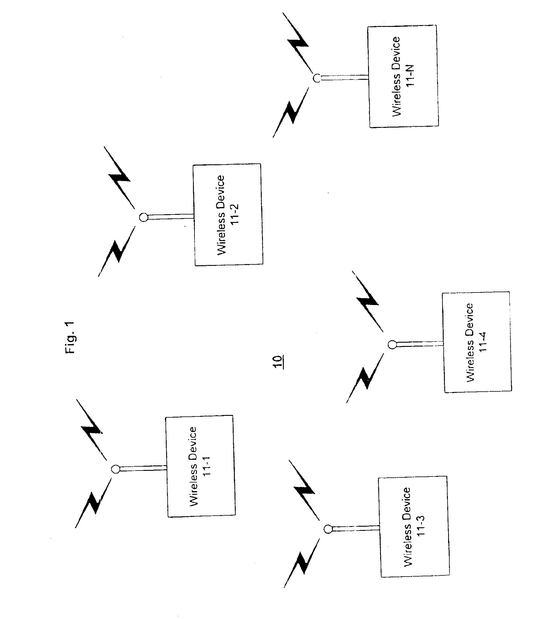
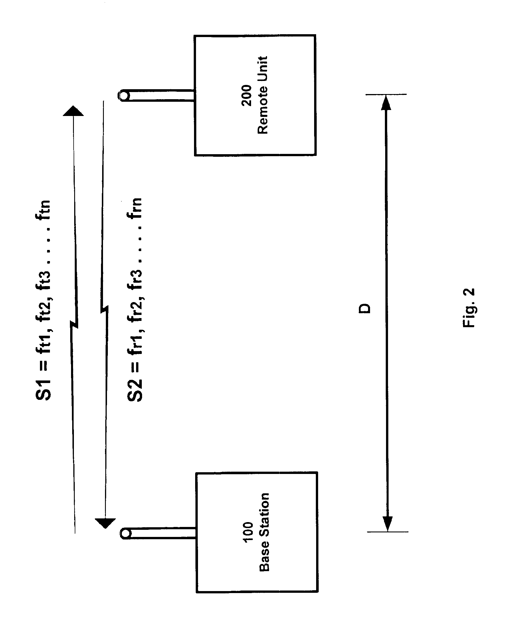
FIG. 1 provides a block diagram illustrating an embodiment of a system 10 in which the present invention may be used. As shown in FIG. 1, the system 10 includes a plurality of wireless devices 11-1 to 11-N (collectively referred to as wireless devices 11) within a particular region. The wireless devices 11 may be communications devices capable of transmitting and receiving information between devices. The information communicated may be data or voice information. At least one and possibly all of the wireless devices 11 are mobile communications devices. For example, the wireless devices 11 may be mobile phones or pagers, or PDAs, handheld computers, laptop computers, or other devices equipped with wireless communications capabilities, or a combination of any of the foregoing. Moreover, the set of wireless devices 11 in the region is not necessarily fixed. Additional wireless devices 11 may enter the region and existing wireless devices 11 may leave the region. It should be understoo...


PUM


Abstract

A system, apparatus, and method for determining the distance between two objects using an indirect propagation delay measurement is disclosed. A frequency hopping scheme (such as the Bluetooth™ technology) is used to measure the relative phase offset of the received signal between the various frequencies. For a given distance between the objects, the phase offset vs. frequency curve is a straight line with the slope dependent upon the measured distance. After the phase of the received signals is detected, the data is plotted on a curve and the slope is calculated.

Description

BACKGROUND OF THE INVENTION1. Field of InventionThe present invention relates to a system and method for measuring a distance between two objects. More specifically, the present invention relates to a system and method of measuring a distance between two objects using RF techniques.2. Description of the Related ArtMobile telephones, pagers, and other wireless communication equipment are now commonplace. More recently, laptop computers, personal digital assistants (PDAs)—such as the Palm™ organizer—have been equipped with wireless communications capabilities. One of the primary benefits of wireless equipment is portability. We can carry our mobile phone with us wherever we go. These wireless devices are currently used for relatively limited purposes, such as making telephone calls, when they are capable of doing much more.One potential use for wireless devices is in mobile commerce. Wireless devices can be used for buying or selling goods or services, making payments, gathering infor...

Claims


Application Information

Patent Timeline
IPC IPC(8): G01S13/00G01S13/84
CPCG01S13/84
Inventor BENSKY, ALANBERLINER, SHLOMOHOLZKANER, URIMIRODIN, EDWARD
Owner AEROSCOUT
Learn More