Excavation system employing a jet pump

a technology of excavating system and jet pump, which is applied in the field of excavating system employing a jet pump, can solve the problems of process instability in the mixing chamber of the device, significant downtime for repair of equipment components, and wear and tear of equipment components, so as to increase the quantity of material moved, increase the energy consumption, and facilitate the effect of changing

Inactive Publication Date: 2005-03-01
WALKER DAWSON INTERESTS
View PDF87 Cites 20 Cited by
  • Summary
  • Abstract
  • Description
  • Claims
  • Application Information

AI Technical Summary

Benefits of technology

The present invention overcomes the shortcoming of prior developments by providing, among other things, a pumping system which can (a) increase the quantity of material moved, relative to previously developed pumps, without an increase in energy consumption, (b) move solid materials with minimal wear on component parts, (c) overcome the problems associated with traditional venturi effect pumps, (d) include specific component parts which are designed to wear and which can be easily changed, (e) produce a vacuum for suctioning material with little or no cavitation, and / or (f) enable the control of the solid to liquid ratio of the material being pumped to drastically increase the pumping efficiency. Moreover, the present invention provides an efficient mixing system which employs a jet pump of this invention and enables users to rapidly form a liquid and solid material mixture, preferably one in which the mixture is substantially homogeneous, to control the weight percent of solids in the resulting mixture, and to efficiently transport the mixture downstream from the jet pump to a desired location.
Thus, in one embodiment of the present invention, an improved liquid jet pump is provided. The liquid jet pump is comprised of a nozzle assembly that pulls in atmospheric air. The liquid jet created by passage of liquid through the nozzle assembly has minimal deflection as it exits because of an atmospheric air bearing surrounding the liquid jet. Consequently, the liquid jet pump has improved efficiency and capacity. The liquid jet pump is configured to define a suction chamber and further comprises a suction pipe. The suction pipe pulls in the material to be pumped as the liquid jet from the nozzle assembly passes through the suction chamber. The liquid jet pump further comprises a target tube that receives the liquid jet combined with material to be pumped which enters the suction chamber after traveling through the suction pipe. The target tube is comprised of a housing support detachable from the suction chamber and a wear plate of abrasion-resistant material.
In yet another embodiment of the present invention, a method of moving, from one location to another, a slurry comprised of a solid and a liquid, is provided. The method comprises:a. injecting a pressurized liquid into a nozzle assembly to produce a flow of pressurized liquid,b. providing a gas to the nozzle assembly to surround the flow of pressurized liquid with the gas,c. directing the flow of pressurized liquid surrounded by the gas into a suction chamber in fluid communication with a suction pipe and an outlet pipe, the outlet pipe defining a venturi-like inner surface, and directing the flow of pressurized liquid surrounded by the gas toward the outlet pipe to produce a vacuum at a free end of the suction pipe, andd. controlling the flow rate of the gas into said nozzle assembly to thereby control the weight ratio of solid to liquid in the slurry so moved.

Problems solved by technology

Because of the abrasive characteristics of particles within such slurry material, these pumps typically suffer wear and tear and significant downtime to repair equipment components, especially moving parts which come into direct contact with the particulate matter.
This technique has typically involved compressed air or gas, requiring expensive compression equipment.
In addition, the combination of gas, water and solids has contributed to process instability in the mixing chamber of the device, as discussed in U.S. Pat. No. 4,681,372.
However, many jet eductor systems are flawed in that their high pressure water jets, while effective at removing high volumes of slurry material, cause severe cavitation in the throat and mixing regions of the eductor conduit, and result in lowered efficiency and extremely short equipment life, as discussed in, e.g., U.S. Pat. No. 4,165,571.
Yet, this system does not produce vacuum sufficient for many commercial operations, and does not provide for control of the weight percentage of solids in pumped slurries.

Method used


Image

  • Excavation system employing a jet pump
  • Excavation system employing a jet pump
  • Excavation system employing a jet pump

Examples


Embodiment Construction

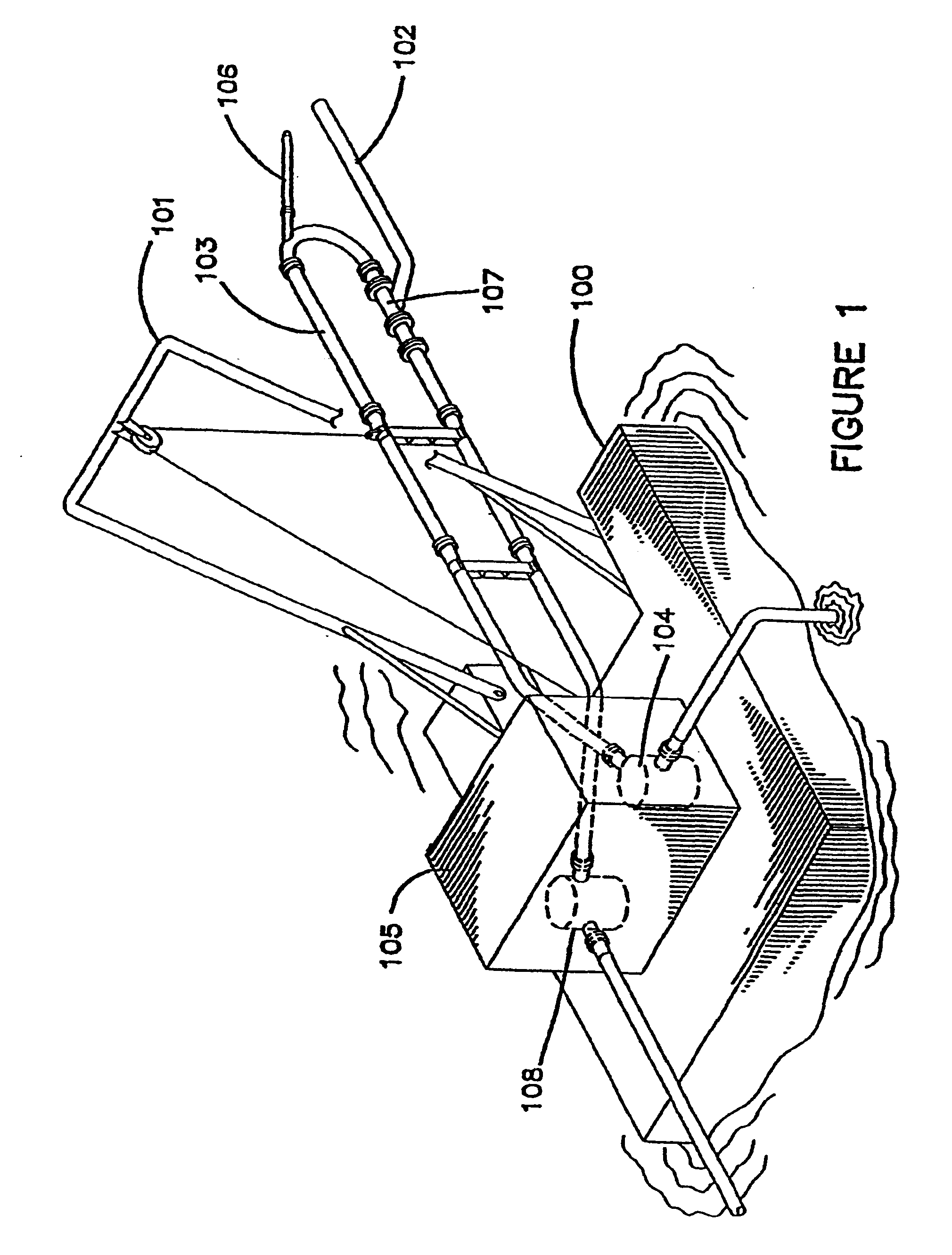
It will now be appreciated that, while specific embodiments are described hereinafter, several other applications of the presently described invention may be contemplated by those of skill in the art in view of this disclosure. For example, while the accompanying drawings illustrate the pumping system of this invention as used for dredging operations, the system may be used for virtually any application in which solid particulate matter, e.g., or a slurry comprised of such matter, must be moved from one location to another. The system also may be employed to remove liquids from each slurry mixtures, thereby permitting solid particulate matter to be rapidly separated from the liquid and dried, if desired. In each of the above examples, small batch operations as well as large commercial batch, semi-continuous and continuous operations are possible using pumping methods and systems of this invention.

The gas employed in the pumping systems and methods of this invention will preferably b...


PUM


Abstract

An excavation system comprises a bucket, defining an outlet at its base, in fluid communication with a suction tube in fluid communication with a jet pump, configured to create a suction in the suction tube. A related method of excavating comprises loading excavation material into a bucket which defines an outlet at its base, sizing the excavation material by sieving action of a guard substantially covering the bucket outlet, and suctioning the sized material though the bucket outlet using a vacuum created by a jet pump.

Description

BACKGROUNDNumerous types of pumps have been developed for moving matter from one location to another. Typically, the physical and / or chemical nature of the material being moved by the pump plays an important role in pump efficacy. For example, the dredging industry commonly utilizes large centrifugal pumps for suction and movement of slurry material, i.e., water or other liquid in admixture with solid particulate matter, e.g., sand or gravel. Because of the abrasive characteristics of particles within such slurry material, these pumps typically suffer wear and tear and significant downtime to repair equipment components, especially moving parts which come into direct contact with the particulate matter.Another dredging technique involves the use of air to induce an upward flow of water. This technique has typically involved compressed air or gas, requiring expensive compression equipment. In addition, the combination of gas, water and solids has contributed to process instability in...

Claims


Application Information

Patent Timeline
Patent Type & Authority Patents(United States)
IPC IPC(8): E02F3/40E02F3/88E02F3/92
CPCE02F3/40E02F3/9212E02F3/90E02F3/8808
Inventor HUTCHINSON, ROBERT J.DAWSON, RICHARD F.
Owner WALKER DAWSON INTERESTS
Why Eureka
Try Eureka