Drive mechanism for a bicycle transmission assist mechanism

a technology of assist mechanism and drive mechanism, which is applied in the direction of mechanical control device, hoisting equipment, instruments, etc., can solve the problems of requiring the rider to move the shift operating device by a correspondingly large amount, and the actuation ratio of some derailleurs may be somewhat larg

Inactive Publication Date: 2005-03-01
SHIMANO INC
View PDF18 Cites 45 Cited by
  • Summary
  • Abstract
  • Description
  • Claims
  • Application Information

AI Technical Summary

Benefits of technology

One of the goals of bicycle transmission design is to make the transmission easy to operate with a minimum amount of effort. This involves minimizing the force needed to operate the shift operating device as well as minimizing the amount of unnecessary movement of the shift operating device. In the case of bicycle transmissions such as derailleurs which are used to shift a chain from one sprocket to another, the amount of force needed to derail the chain from one sprocket and move it to another can be quite large, especially when the destination sprocket is substantially larger than the originating sprocket and the rider is exerting substantial pedaling force on the chain. The necessary operating force can be reduced by operating the shift operating device when only a small pedaling force is being applied to the chain, but that requires the rider to consciously alter his or her pedaling technique and / or consciously operate the shift operating device only when a small pedaling force is being applied to the chain. That can be very distracting, especially in a racing environment. Also, the actuation ratio of some derailleurs may be somewhat large. Consequently, the shift operating wire must move a substantial distance to fully move the chain from one sprocket to another, thus requiring the rider to move the shift operating device by a correspondingly large amount.

Problems solved by technology

That can be very distracting, especially in a racing environment.
Also, the actuation ratio of some derailleurs may be somewhat large.
Consequently, the shift operating wire must move a substantial distance to fully move the chain from one sprocket to another, thus requiring the rider to move the shift operating device by a correspondingly large amount.

Method used


Image

  • Drive mechanism for a bicycle transmission assist mechanism
  • Drive mechanism for a bicycle transmission assist mechanism
  • Drive mechanism for a bicycle transmission assist mechanism

Examples


Embodiment Construction

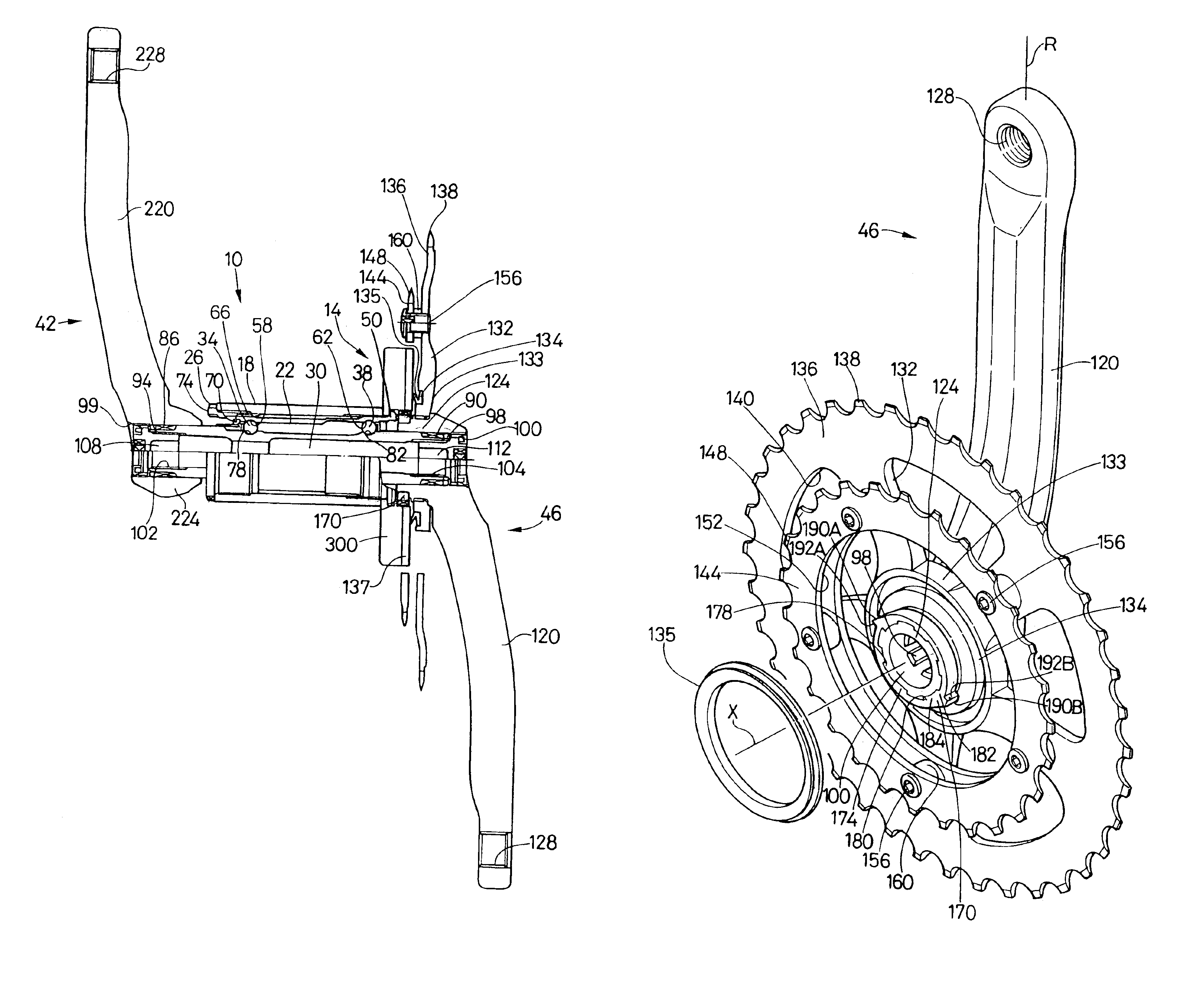
FIG. 1 is a partial cross sectional view of a bicycle bottom bracket assembly 10 that incorporates a particular embodiment of an assisting apparatus 14 according to the present invention for shifting a bicycle transmission. Bottom bracket assembly 10 includes a bottom bracket shell 18 that is mounted to a typical bicycle frame (not shown), a tubular axle supporting sleeve 22, a sleeve coupler 26, an axle 30, ball bearings 34 and 38, and crank arm assemblies 42 and 46. Axle supporting sleeve 22 has a radially outwardly extending flange 50 on a first end thereof for retaining a mounting member 300 of assisting apparatus 14 to bottom bracket shell 18, bearing surfaces 58 and 62 for engaging ball bearings 34 and 38, respectively, and an outer peripheral surface 66 at a second end for engaging an inner peripheral surface 70 of sleeve coupler 26. Sleeve coupler 26 includes a radially outwardly extending flange 74 for engaging the side of bottom bracket shell 18.

In this embodiment, axle 30...


PUM


Abstract

A drive mechanism for a bicycle transmission assist mechanism includes a crank arm having a drive member. The drive member includes a first abutment facing a forward rotational direction of the crank arm and a non-concave sloped surface facing a rearward rotational direction of the crank arm.

Description

The present invention is directed to control devices for bicycle transmissions and, more particularly, to an apparatus that uses rotational power from a rotating crank, axle or some other member to assist the operation of the bicycle transmission.A typical bicycle transmission is operated by a shift operating wire connected between the transmission and a manually operated shift operating device mounted on the handlebar. The rider operates the shift operating device to selectively pull or release the shift operating wire which, in turn, operates the transmission in the desired manner.One of the goals of bicycle transmission design is to make the transmission easy to operate with a minimum amount of effort. This involves minimizing the force needed to operate the shift operating device as well as minimizing the amount of unnecessary movement of the shift operating device. In the case of bicycle transmissions such as derailleurs which are used to shift a chain from one sprocket to anot...

Claims


Application Information

Patent Timeline
Patent Type & Authority Patents(United States)
IPC IPC(8): B62M9/04B62M9/00B62M25/00B62M25/02B62M9/10B62M9/1242B62M9/1346G05G1/48
CPCB62M3/003B62M9/04B62M25/02Y10T74/2165Y10T74/2164Y10T74/2101
Inventor NANKO, YOSHIAKIYAMANAKA, MASAHIROTETSUKA, TOSHIO
Owner SHIMANO INC
Why Eureka
Try Eureka