Subsoil fertilizer applicator

a fertilizer applicator and soil technology, applied in the field of soil fertilizer applicators, can solve the problems of shortening the useful life of parts, difficult to accurately and consistently apply proper fertilizer amounts, and affecting the flow of soil, so as to reduce the chance of premature wear, and enhance the effect of soil flow

Inactive Publication Date: 2005-03-01
GREAT PLAINS MFG INC
View PDF12 Cites 22 Cited by
  • Summary
  • Abstract
  • Description
  • Claims
  • Application Information

AI Technical Summary

Benefits of technology

The present invention provides a subsoil applicator and furrow loosening device that minimizes the opportunities for plugging the discharge outlets and reduces the opportunities for premature wear of the fertilizer delivery structure. It also enhances soil flow and achieves improved loosening or fluffing action while at the same time having greater resistance to premature wear.
In one preferred embodiment of the invention, the applicator has the fertilizer delivery structure housed internally within the shank and wings of the device, with the wings having laterally offset and rearwardly facing discharge outlets through which the fertilizer passes out of the device and into the soil. A thickened rear portion of the wings pre

Problems solved by technology

In some soil conditions, these openings can become plugged, making it difficult to accurately and consistently apply proper amounts of fertilizer.
Moreover, the discharge tube is exposed to wear from abrasive soil, which shortens its useful life.
In addition, an upwardly inclined rear portion on the wings just ahead of the discharge tube does not provide the optimum soil

Method used


Image

  • Subsoil fertilizer applicator
  • Subsoil fertilizer applicator
  • Subsoil fertilizer applicator

Examples


Embodiment Construction

The present invention is susceptible of embodiment in many different forms. While the drawings illustrate and the specification describes certain preferred embodiments of the invention, it is to be understood that such disclosure is by way of example only. There is no intent to limit the principles of the present invention to the particular disclosed embodiments.

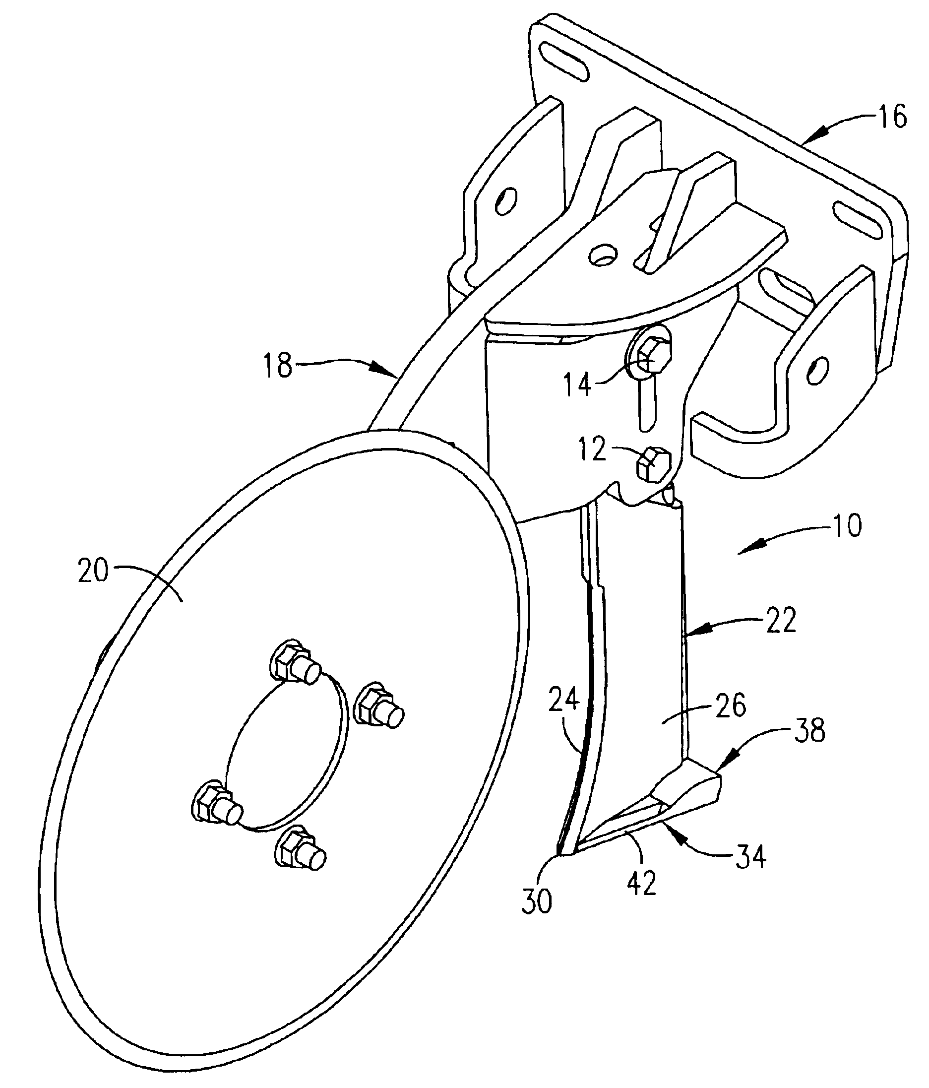
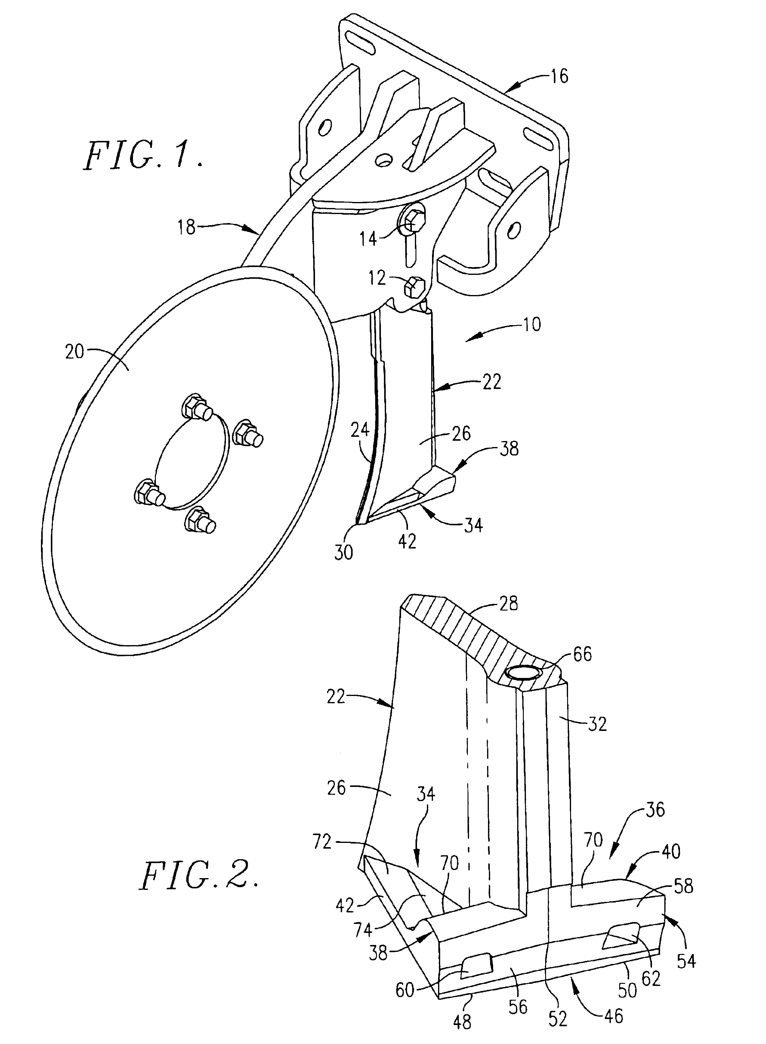
With initial reference to FIG. 1, the applicator 10 is shown attached by bolts 12 and 14 to a mounting bracket broadly denoted by the numeral 16 which is adapted to be secured to the front of a planter opener (not shown) so that applicator 10 moves along directly in front of the opening device that is depositing seeds into the soil. Also secured to bracket 16 by welding or otherwise is a coulter wheel assembly 18 including a coulter 20 positioned in direct frontal alignment with applicator 10 for cutting through trash during field operations and facilitating entry of applicator 10 into the soil. Coulter 20 also serves to pro...


PUM


Abstract

A subsoil applicator has an upright shank provided with a leading soil-slicing edge and a pair of opposite sides. At the bottom of the shank, a pair of soil lifting wings are provided, presenting a pair of outermost wing edges that diverge rearwardly from the lowermost and forwardmost point of the shank to the rear extremity of the applicator. The wings are generally relatively thin and flat except for a thickened portion across their rear extremity making an upright, rearwardly facing rear wall. A pair of laterally spaced discharge outlets are located in the rear wall and communicate with an internal tubular passage within the shank for delivering substance down into the soil behind the wall as the applicator advances through the soil. The discharge outlets are located in undercut portions of the rear wall, while top, upwardly facing surfaces of the thickened portion are convexly curved to improve soil flow and provide extra protection against premature wear for the internal substance passageways.

Description

TECHNICAL FIELDThis invention relates to tillage equipment and, more particularly, to a subsoil applicator which may be used to apply starter fertilizer or the like at the same time it opens a seed furrow for accepting seeds from a trailing planter opener.BACKGROUND AND SUMMARYIt is known in the art to cut a seed furrow with an upright shank or knife and simultaneously fluff the furrow sidewalls with laterally projecting wings while placing fertilizer in an offset manner along the seed line of the furrow. See for example U.S. Pat. No. 5,495,814 to David R. Primus titled Sub-zone Tiller with Offset Fertilizer Placement.However, in the Primus tiller fertilizer is applied through a transversely extending cross tube at the rear of the device that has a pair of discharge openings at its opposite ends. In some soil conditions, these openings can become plugged, making it difficult to accurately and consistently apply proper amounts of fertilizer. Moreover, the discharge tube is exposed to...

Claims


Application Information

Patent Timeline
IPC IPC(8): A01B15/00A01B15/02A01C5/00A01C5/06
CPCA01C5/062A01B15/025
Inventor ROBILLARD, JEROME
Owner GREAT PLAINS MFG INC
Why Eureka
Try Eureka