Jet barrel for a spa jet

Active Publication Date: 2005-03-01
GUANGZHOU RISING DRAGON RECREATION IND CO LTD
View PDF30 Cites 46 Cited by
  • Summary
  • Abstract
  • Description
  • Claims
  • Application Information

AI Technical Summary

Benefits of technology

Preferably, the means to support the rotor is a spindle pin which is supported for co-rotation with the rotor at an upstream and downstream end of the jet barrel. The downstream pivot point, preferably a stainless steel inset, is fit within a hub supported at the center of a jet barrel face by a plurality of angled vanes. The insert provides a surface against which the spindle pin is contacted axially and upon which it can rotate. Further, the arrangement is insensitive to buildup of hard water deposits land the like. The upstream pivot point comprises an upset having a small bore which aids in positioning the spindle pin radially along at the longitudinal axis and permits the spindle pin to rotate loosely therein. As the bore is not a bearing surface, it is sized sufficiently with a clearance to permit rotation of the pin therein without interference from hard water deposits and the like.
More preferably, the jet barrel has a second inlet, positioned downstream from the first inlet and adapted to be positioned against a second inlet in the spa jet housing through which a stream of pressurized air can be admitted to the water stream for enhancing the flow of water through the jet barrel.

Problems solved by technology

Further, the arrangement is insensitive to buildup of hard water deposits land the like.

Method used


Image

  • Jet barrel for a spa jet
  • Jet barrel for a spa jet
  • Jet barrel for a spa jet

Examples


Embodiment Construction

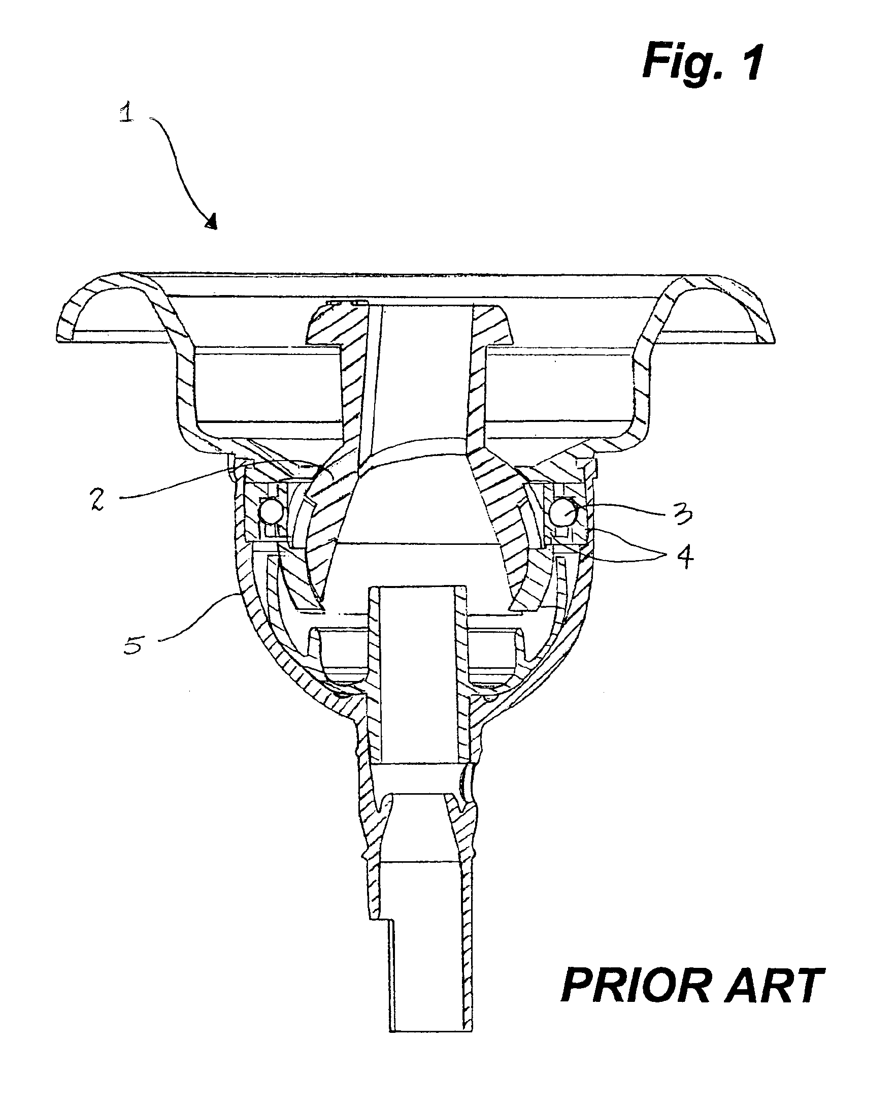
According to FIG. 1, a prior art spa jet 1 is shown. A semicircular nozzle 2 is supported by ball bearings 3 in bearing races 4 for rotation within a housing 5. Water, flowing through the bearing races 4 and around the nozzle 2, causes hard water deposits and debris to build-up, resulting in eventual plugging and cessation of rotation.

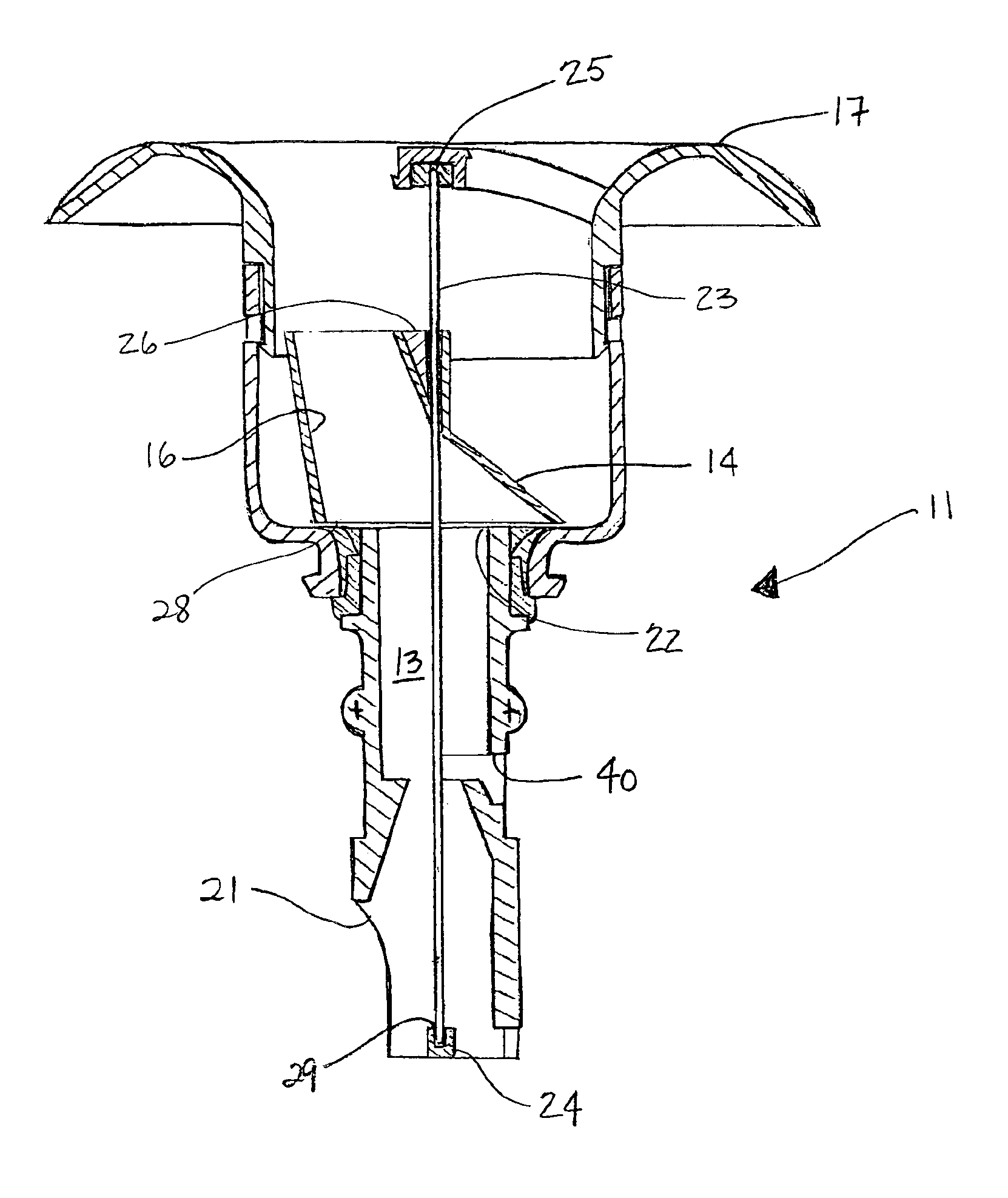
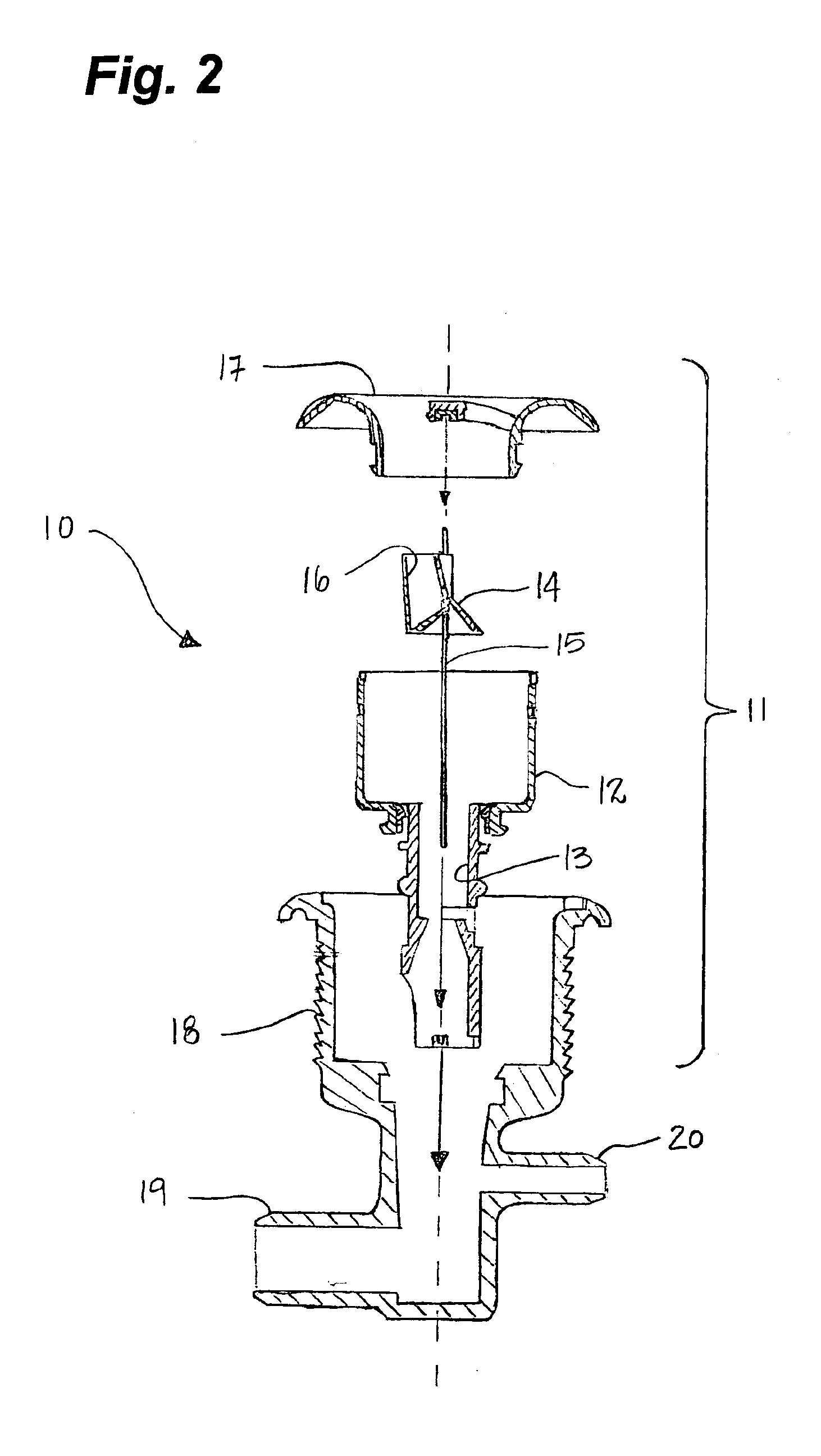
Having reference to FIG. 2, a spa jet 10 comprising one embodiment of a spa jet barrel 11 of the present invention is shown. The spa jet barrel 11 further comprises a jet barrel housing 12 defining a bore 13 and having a longitudinal axis, a rotor 14, means 15 for rotatably supporting the rotor 14 in the bore 13, a tubular nozzle 16 fluidly connected to the rotor 14 and extending at an angle offset from the longitudinal axis and a jet barrel face 17. The jet barrel 11 is adapted for fitting within a spa jet housing 18, having a first inlet 19 connected to a pressurized water source, and optionally, a second inlet 20 positioned downstream from the first...


PUM


Abstract

A jet barrel adapted for use in a spa jet housing having a rotor rotatably supported on a spindle pin aligned along a longitudinal axis in the bore of the jet barrel. The spindle pin is supported at upstream and downstream pivot points. An offset nozzle extends from a conical base of the rotor, an inlet to the rotor being aligned with an outlet from the jet barrel's bore. As water exits the jet barrel bore into the rotor, the rotor and spindle pin are caused to co-rotate. Hard water deposits, sufficient to prevent rotation do not readily build around the pivot points.

Description

FIELD OF THE INVENTIONThe invention relates to spa jets for a hot tub or hydrotherapy tub and more particularly relates to spa jets having a jet barrel and a nozzle rotatably fixed within the jet barrel for minimizing clogging in the jet barrel which would prevent rotation.BACKGROUND OF THE INVENTIONIt is known to use rotary jets in a spa to direct a stream of water through one or more nozzles which rotate, to provide a swirling or agitating motion to the water which acts against the users skin and muscle tissue.Typically, as taught in U.S. Pat. No. 6,123,274 to Perdreau et al., spa jets of this type have a housing which is connected at an inlet to a pressurized water source. A nozzle is supported in a jet barrel in the housing by a radial ball bearing in an open cup-shaped portion of the jet barrel. The nozzle typically has an angular passage, radially offset from the central axis of the housing and jet barrel so that as the water enters the inlet and is caused to exit the passage,...

Claims


Application Information

Patent Timeline
Patent Type & Authority Patents(United States)
IPC IPC(8): A61H33/00A61H33/02B05B3/02B05B3/06
CPCA61H33/027B05B3/06A61H33/6063
Inventor AMENDT, DARCY S.VAN'T HOFF, M. PETER
Owner GUANGZHOU RISING DRAGON RECREATION IND CO LTD
Why Eureka
Try Eureka