Arc discharge suppressive terminal pair

a terminal and arc discharge technology, applied in the field of terminal pairs, can solve the problems of terminal damage, contact failure with the female terminal, difficulty or inability of the female terminal to be inserted into the female terminal, etc., and achieve the effect of preventing deformation and damage of the terminal pair

Inactive Publication Date: 2005-03-01
AUTONETWORKS TECH LTD +2
View PDF8 Cites 25 Cited by
  • Summary
  • Abstract
  • Description
  • Claims
  • Application Information

AI Technical Summary

Benefits of technology

It is another object of this invention to provide a pair of terminals that enables to effectively suppress occurrence of arc discharge at the time of detachment or disengagement of the terminals and to suppress deformation and damage of the terminals due to occurrence of arc discharge.
In the above arrangement, since the final contact portion is covered with the arc discharge suppressive layer containing the high-melting metal, effectively suppressed is occurrence of arc discharge at the time of disengagement of the terminal pair, thereby preventing deformation and damage of the terminal pair due to occurrence of arc discharge.

Problems solved by technology

Therefore, it is highly likely that the terminals may be damaged due to occurrence of such large arc discharge.
In other words, the male terminal is likely to be deformed due to melting by repeated arc discharges, which may result in contact failure with the female terminal or, in a worse case, difficulty or inability of its insertion into the female terminal.

Method used


Image

  • Arc discharge suppressive terminal pair
  • Arc discharge suppressive terminal pair
  • Arc discharge suppressive terminal pair

Examples


examples

Hereinafter, this invention is described by means of the following examples. It should be noted that the invention is not limited by the examples and that any modification and alteration of this invention which does not depart from the spirit of essential characteristics of the aforementioned and below-mentioned description are construed to be embraced in the technical range of this invention.

examples 1 through 7

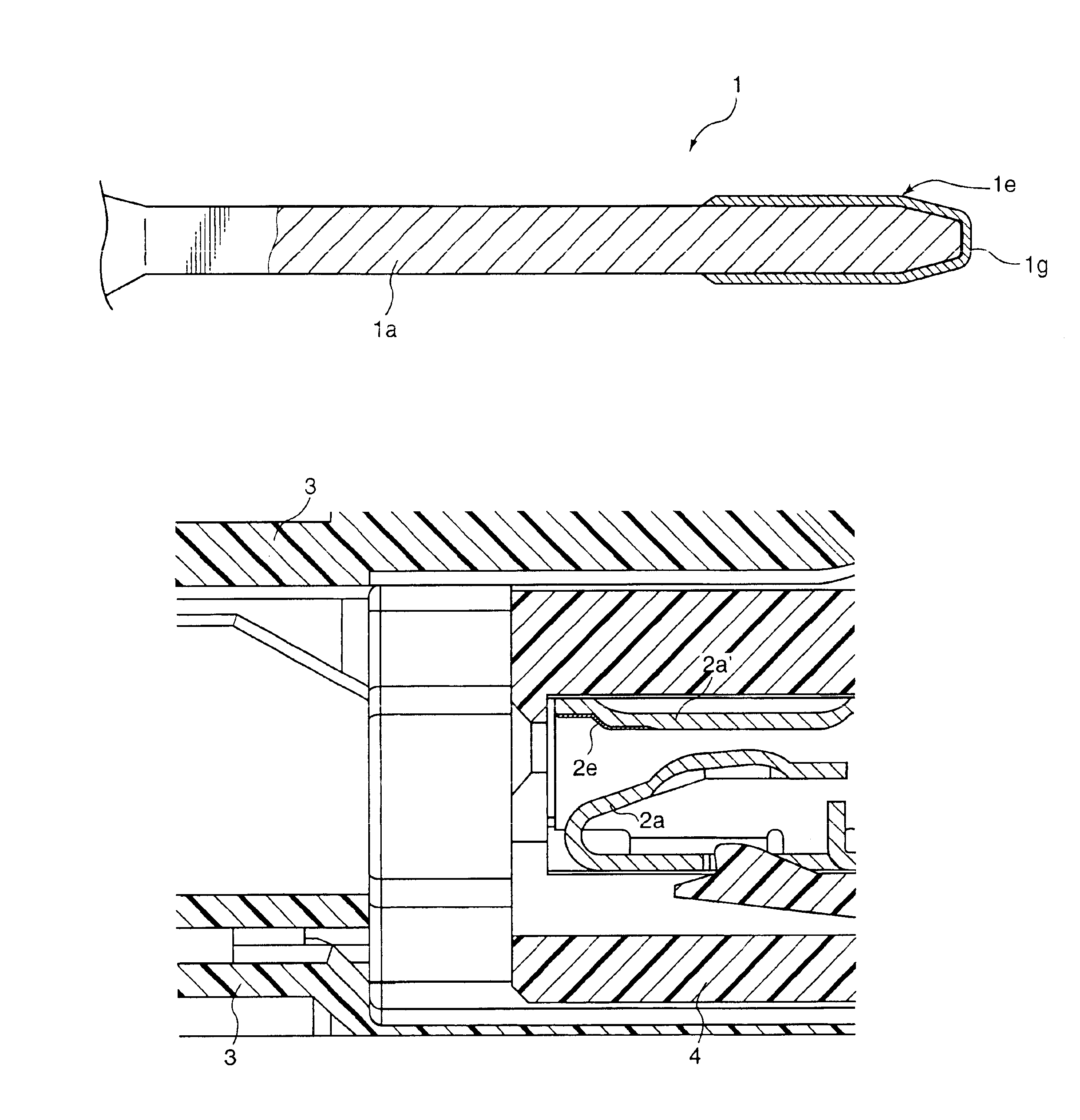
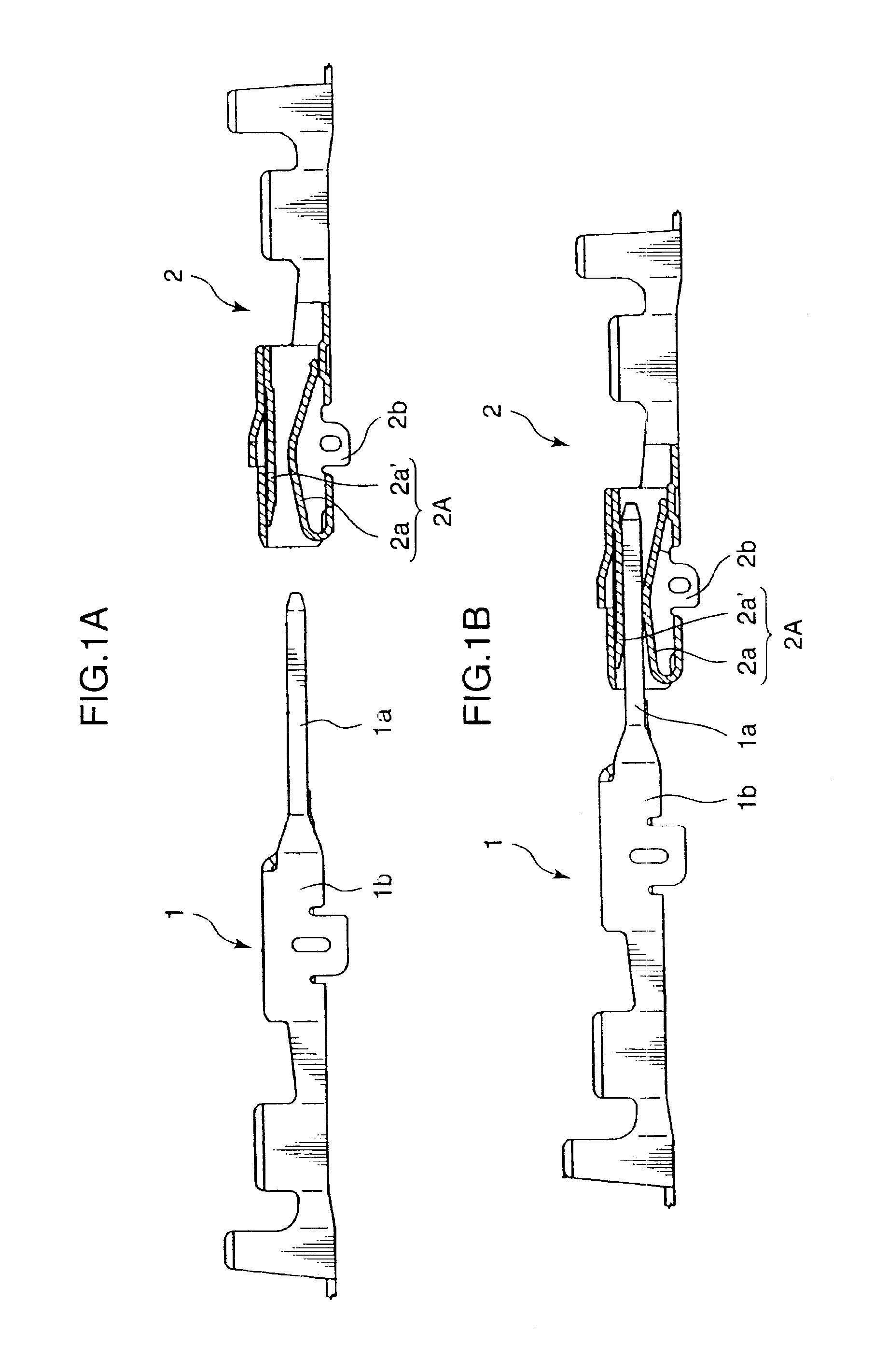
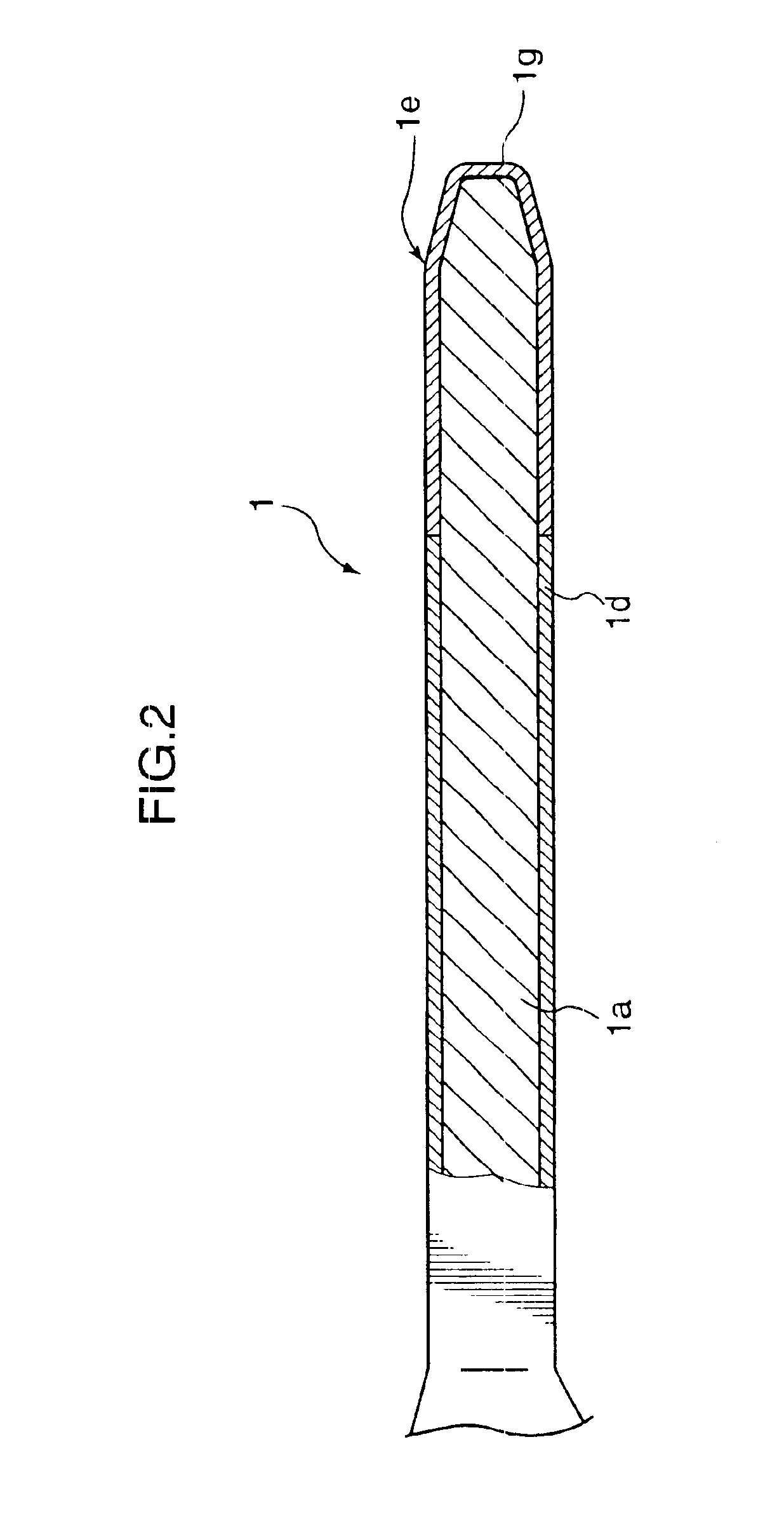
Respective sets of the male tab 1a and the female-type electric contact portion 2A shown in FIGS. 1A through 4 were applied with a corresponding plating as shown in Table 1. In each example, the male tab 1a was tightly received in the female-type electric contact portion 2A until the male terminal 1 and the female terminal 2 were brought to a completely engaged state as shown in FIG. 3. Thereafter, the male terminal 1 was detached from the female terminal 2. The engagement and disengagement (detachment) were repeated a certain number of times while applying a voltage of 36V (current of 10A at the time of engagement) until a large arc discharge accompanied by glaring light occurred. Counted was the number of times during which the engagement and disengagement could carried on without causing large arc discharge.

The results of the experiment are shown in Table 1.

TABLE 1Kind of PlatingMale tab 1aFemale-type contact portion 2ALead end portionBase endspring pieceNumber ofEx(region having...


PUM


Abstract

Provided is a pair of arc discharge suppressive terminals electrically communicable with each other by engagement of the terminal pair. At least one of the terminal pair has a final contact site which is in contact with the counterpart terminal at a final stage of disengagement of the terminal pair. At least the final contact site is covered with an arc discharge suppressive layer containing a first metal having a melting point of 1,550° C. or higher. It is preferable that the terminal pair contact with each other at a portion corresponding to a main contact site other than the arc discharge suppressive layer in a completely engaged state where the one of the terminal pair and the counterpart terminal are tightly engaged with each other. Preferably, the main contact site has a surface made of a material having a higher conductivity than the arc discharge suppressive layer. This arrangement effectively suppresses occurrence of arc discharge at a time of disengagement of the terminal pair.

Description

BACKGROUND OF THE INVENTION1. Field of the InventionThis invention relates to a terminal pair for use in electrical connection in an automobile or the like.2. Description of the Related ArtIt is a general practice to detach connectors used in automobiles or the like from each other every several months or every several years for maintenance and checkup. It is high likely that arc discharge may occur at a detachment of terminals of the connectors from each other. Particularly, it is conceivable that a considerably large amount of arc is discharged in view of the recent development of technology in which a high source voltage is supplied for a battery of an automobile. Therefore, it is highly likely that the terminals may be damaged due to occurrence of such large arc discharge.Generally, a male terminal has a bar-like or a plate-like shape with a lead end thereof tapered in order to facilitate its insertion into a female terminal. Every time the male terminal is disengaged from and e...

Claims


Application Information

Patent Timeline
Patent Type & Authority Patents(United States)
IPC IPC(8): H01R13/03
CPCH01R13/03
Inventor OTA, KOUJIHIRAI, HIROKITSUJI, YOSHITSUGUTAKANO, SATOSHISHIBATA, MASAHIROKIMURA, ATSUSHIKANDA, MASAHIKOYAGI, NARITOHAYASHI, NORIKI
Owner AUTONETWORKS TECH LTD
Why Eureka
Try Eureka