
Methods for collecting body fluid

a body fluid and collection method technology, applied in the field of body fluid testing, can solve the problems of logic circuits having a built-in time delay, small fluid volumes, and additional challenges for analyte testing,

Inactive Publication Date: 2005-03-01
INTEG
View PDF104 Cites 32 Cited by
  • Summary
  • Abstract
  • Description
  • Claims
  • Application Information

AI Technical Summary

Benefits of technology

This approach ensures reliable testing by preventing premature fluid contact with test components, reducing evaporation, and allowing accurate analysis with minimal sample volume, ensuring that testing only commences when an adequate sample is collected, thereby improving the reliability and efficiency of analyte testing.

Problems solved by technology

However, small fluid volumes present additional challenges for analyte testing.
Such premature deposit may initiate chemical reactions on a test strip thereby consuming reagents before a reliable test can be initiated.
A premature deposit of an inadequate volume of fluid sample may falsely inform logic circuits that testing has initiated when, in fact, an adequate sample volume has yet to be collected.
For example, logic circuits may have a built-in time delay which assumes a fixed period of time to collect an adequate volume of sample.
Of course, such systems suffer from the fact there is no certainty that an adequate volume is collected during such time delay.
Alternatively, to be conservative, such time delays may frequently be unnecessarily long.
However, such a system suffers from chemical agents on the membrane being in contact with a sample prior to initiating testing.

Method used


Image

  • Methods for collecting body fluid
  • Methods for collecting body fluid
  • Methods for collecting body fluid

Examples


Embodiment Construction

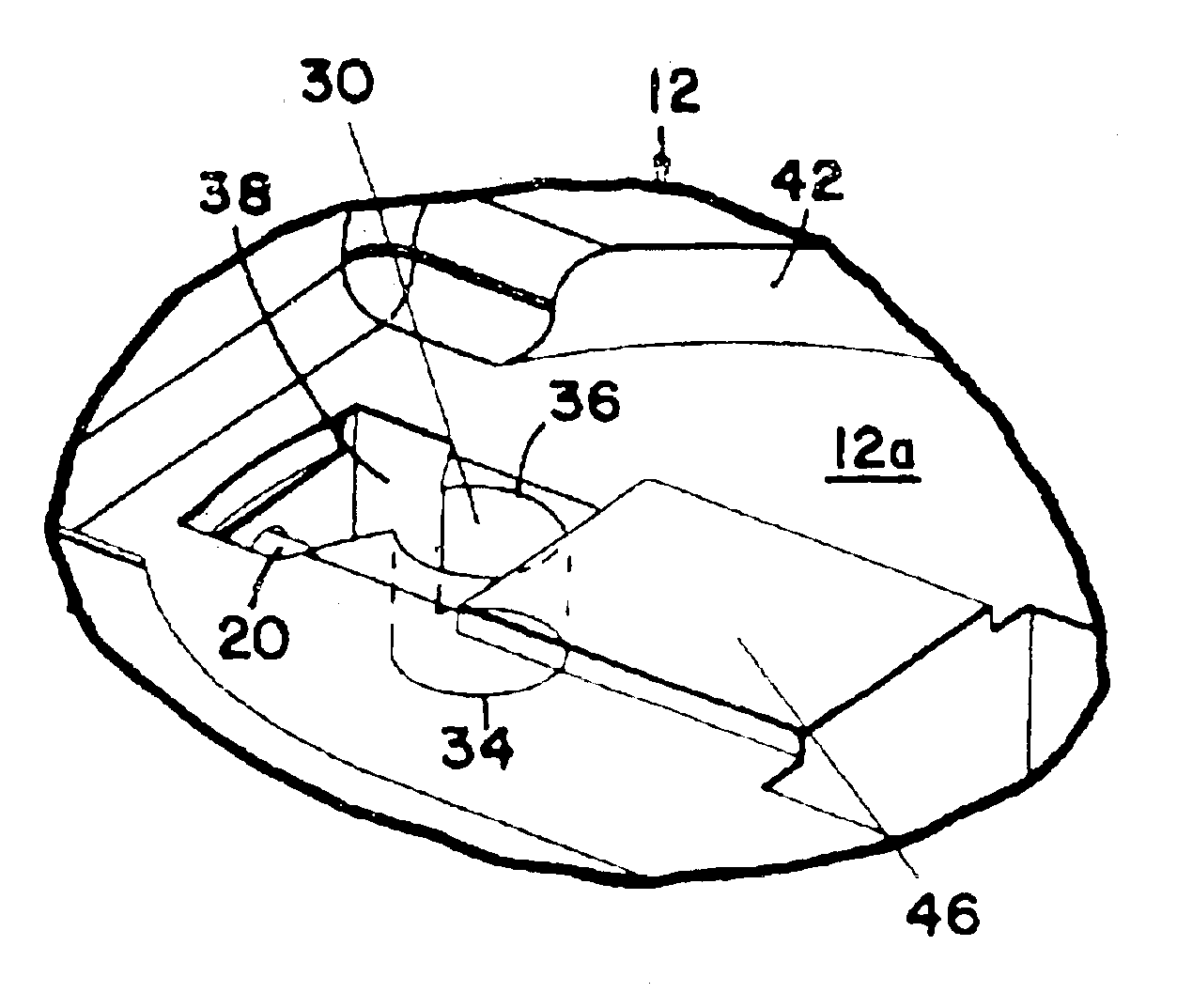
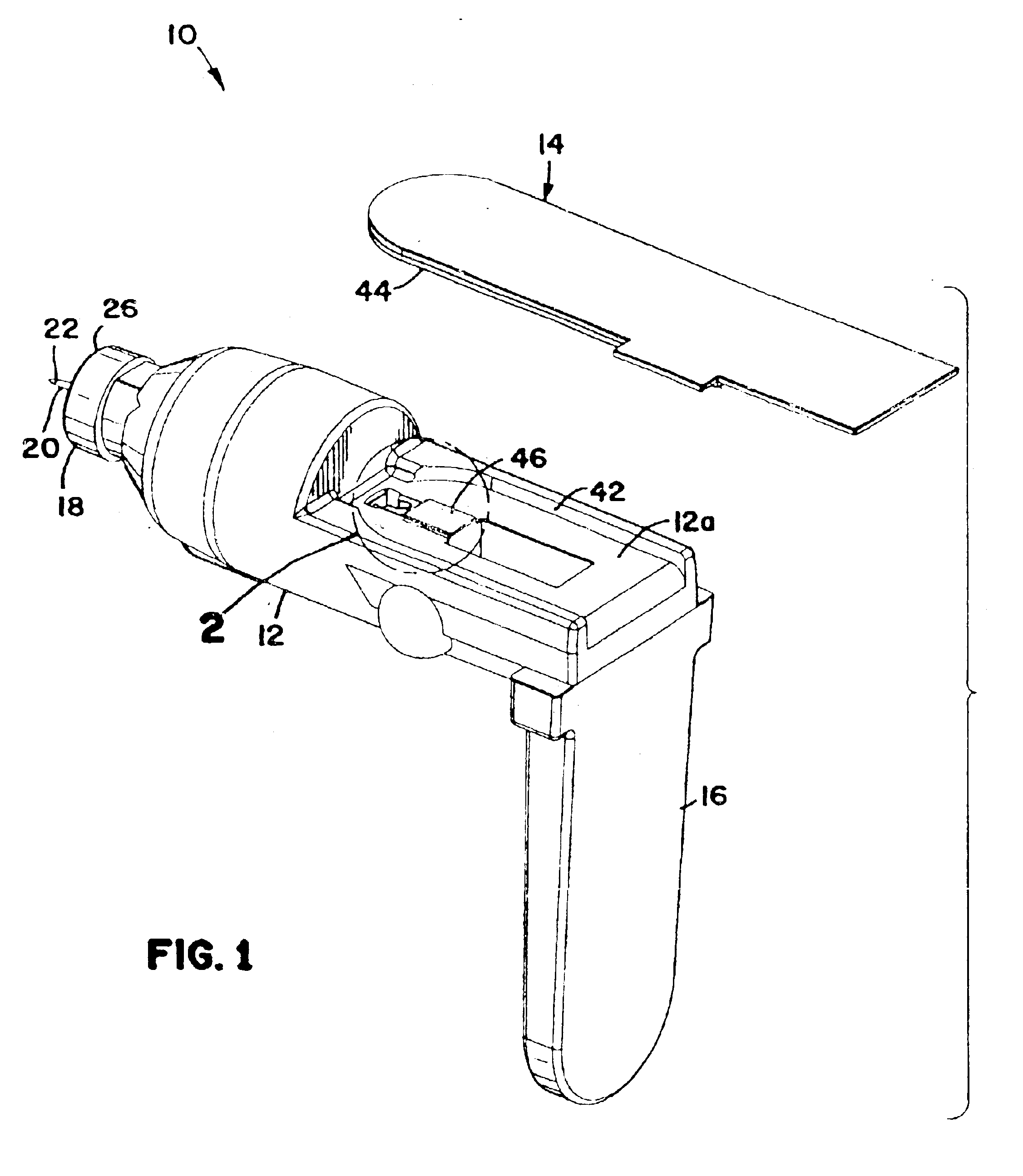
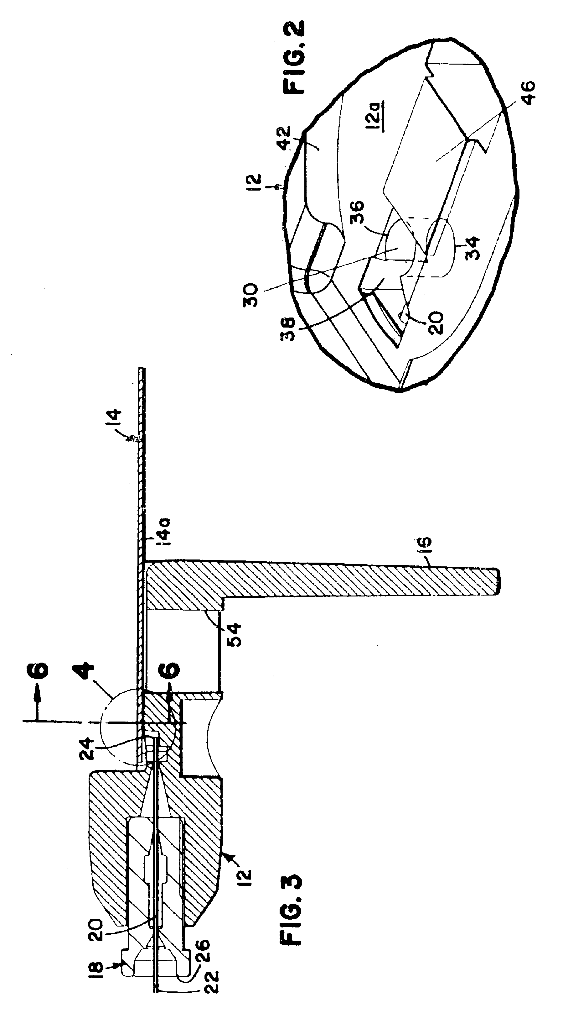
With reference to the various drawing figures in which identical elements are numbered identically throughout, a description of a preferred embodiment will now be provided. Throughout this description, the present invention will be described with reference to collecting a sample of interstitial fluid for glucose testing using a narrow needle that penetrates into, but not through, the dermis as more fully described in commonly assigned U.S. Pat. Nos. 5,823.973 and 5.820,570, the disclosures for both of which are hereby incorporated herein by reference. While such a use is a preferred embodiment, the present invention is applicable to other fluid collection systems (e.g., blood collection) as well as testing for other fluid analytes. Further, the present invention is described with reference to using electro-chemical testing of a collected sample. The teachings of the present invention are equally applicable to other testing methods such as colormetric testing and IR absorption testin...


PUM

PropertyMeasurementUnit
volumeaaaaaaaaaa
volumesaaaaaaaaaa
outer diameteraaaaaaaaaa

Abstract

A body fluid is collected for testing for an analyte contained within the body fluid. The fluid is collected in an apparatus including a reservoir for receiving and collecting a flow of body fluid from a discharge end of a conduit. A capillary test space is in fluid flow communication with the reservoir. The capillary test space is positioned to be in contact with the fluid in the reservoir after the fluid has accumulated to a predetermined transfer volume of fluid. The capillary test space is sized to wick the fluid from the reservoir when the fluid contacts the capillary test space.

Description

TECHNICAL FIELDThis invention pertains to testing a body fluid for an analyte. For example, the present invention is applicable for testing glucose in a body fluid such as blood or interstitial fluid.BACKGROUNDNumerous patents teach various ways for collecting a sample of body fluid and testing such fluid for an analyte such as glucose. For example, U.S. Pat. Nos. 5,823,973 and 5,820,570 describe methods and apparatus for obtaining, in one embodiment, interstitial fluid, which is tested for glucose through IR absorption. These patents also describe use of the disclosed inventions in colormetric and electro-chemical testing of glucose. U.S. Pat. No. 5,453,360 teaches a test strip for colormetric testing for glucose. Blood is placed on a test strip containing various chemical components including a dye. The degree of color change of the test strip indicates the amount of glucose. U.S. Pat. Nos. 5,508,171 and 5,628,890 teach electro-chemical testing. Blood is placed on a test strip con...

Claims


Application Information

Patent Timeline
Patent Type & Authority Patents(United States)
IPC IPC(8): A61B5/00A61B5/15B01L3/00G01N33/487A61B5/145G01N33/48A61B5/1468A61B5/157G01N27/28G01N27/416G01N33/483
CPCA61B5/1411A61B5/14532A61B5/1486B01L3/5027B01L3/502715A61B5/150022A61B5/150259A61B5/150358A61B5/150389A61B5/150519A61B5/15105A61B5/15142A61B5/157A61B5/14514Y10T436/2575A61B2562/0295B01L3/5023B01L3/50273B01L3/502738B01L2200/026B01L2200/0621B01L2200/0684B01L2200/143B01L2300/0645B01L2300/069B01L2300/0825B01L2300/161B01L2400/0406
Inventor ALLEN, JOHN J.RACCHINI, JOEL R.
Owner INTEG
Learn More