Method for cooling a hot-rolled material and corresponding cooling-line models

Inactive Publication Date: 2005-03-01
PRIMETALS TECH GERMANY
View PDF4 Cites 36 Cited by
  • Summary
  • Abstract
  • Description
  • Claims
  • Application Information

AI Technical Summary

Benefits of technology

The advantage of this approach consists in the possibility of linking it to Fourier's heat conduction equation without having to renounce the

Problems solved by technology

However, the methods of the prior art only appear to solve the problem.
In

Method used


Image

  • Method for cooling a hot-rolled material and corresponding cooling-line models
  • Method for cooling a hot-rolled material and corresponding cooling-line models
  • Method for cooling a hot-rolled material and corresponding cooling-line models

Examples


Embodiment Construction

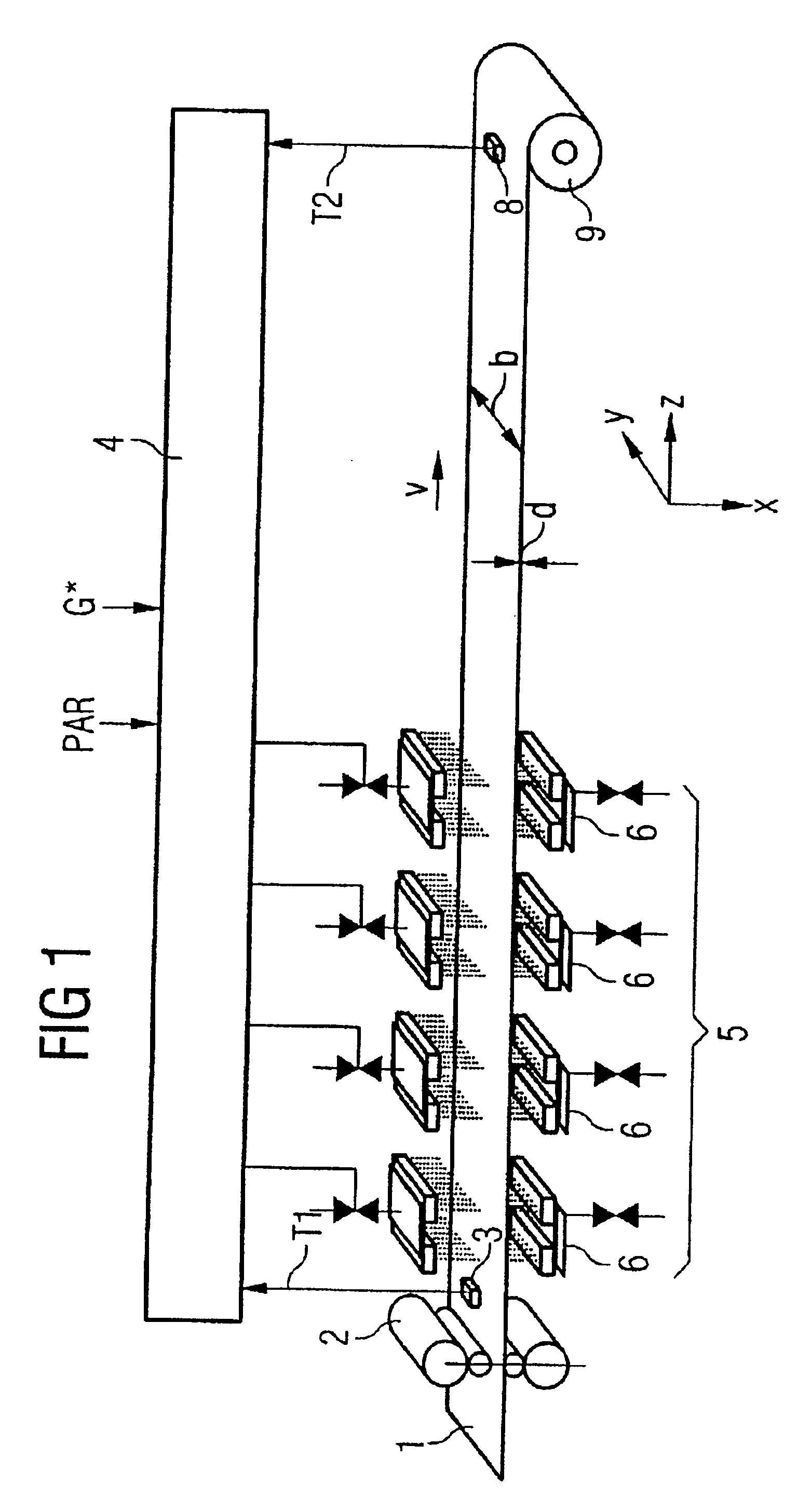
As shown in FIG. 1, a hot-rolled material 1 runs out of a rolling stand 2 in a strip running direction z and at a rolling speed v. Downstream of the rolling stand 2 there is a rolling-stand temperature-measuring point 3. In the rolling-stand temperature-measuring point 3, a starting temperature T1 for a rolled-material location is recorded at the surface of the rolled material 1 and is fed to a cooling-line model 4 as an input parameter.

In accordance with FIG. 1, the rolled material 1 is a metal strip, e.g. a steel strip. Therefore, in the width direction y, it has a rolled-material width b and, in a thickness direction x, a rolled-material thickness d. Rolled-material width b and rolled-material thickness d together result in the rolled-material cross section of the rolled material 1.

The starting temperature T1 of the rolled material 1 may vary transversely across the strip width b. The rolled-material temperature-measuring point 3 is therefore preferably designed in such a manner ...


PUM

PropertyMeasurementUnit
Temperatureaaaaaaaaaa
Densityaaaaaaaaaa
Phaseaaaaaaaaaa

Abstract

To determine the temperature profile (Tm(t)) of a hot-rolled material (1) in a cooling line (5), a heat conduction equation which takes the following form et-div[λ(e,p)ρ·gradT(e,p)]=0
where e is the enthalpy, λ the thermal conductivity, p the degree of phase transformation, ρ the density and T the temperature of the rolled material at the rolled-material location and t is the time, is solved in a cooling-line model (4).

Description

BACKGROUND OF THE INVENTIONThe present invention relates to a method for cooling a hot-rolled material having a rolled-material cross section, in particular a metal strip, e.g. a steel strip, in a cooling line, comprising the following steps:a starting temperature is recorded for a rolled-material location upstream of the cooling line,a temporal quantitative coolant profile is determined on the basis of a cooling-line model and predetermined desired properties of the rolled material,a coolant is applied to the rolled-material location in accordance with the temporal quantitative coolant profile which has been determined, andan expected temporal temperature profile of the rolled material at the rolled-material location across the rolled-material cross section is determined on the basis of the cooling-line model and the temporal quantitative coolant profile.The present invention also relates to a corresponding cooling-line model.A cooling method of this type and the corresponding cool...

Claims


Application Information

Patent Timeline
IPC IPC(8): B21B37/74B21B37/76C21D11/00C21D9/573B21B45/02
CPCB21B37/76C21D11/005C21D9/573B21B2273/20
Inventor FRANZ, KLAUSWEINZIERL, KLAUS
Owner PRIMETALS TECH GERMANY
Why Eureka
Try Eureka