
Device for the regulation of a plasma impedance

a technology of plasma impedance and device, which is applied in the direction of plasma technique, energy-based chemical/physical/physico-chemical processes, pressurized chemical processes, etc., can solve the problems of difficult attainment of stable operation transition range and relative high effort and expenditur

Inactive Publication Date: 2005-03-01
APPLIED MATERIALS GMBH & CO KG
View PDF13 Cites 18 Cited by
  • Summary
  • Abstract
  • Description
  • Claims
  • Application Information

AI Technical Summary

Problems solved by technology

However, in the case of high powers and / or cathode spacings a stable operation transition range is often difficult of attainment since an uncontrolled toggling from the metallic into the fully reactive mode occurs readily.
Such instantaneous value acquisition requires relative high effort and expenditures.

Method used


Image

  • Device for the regulation of a plasma impedance
  • Device for the regulation of a plasma impedance
  • Device for the regulation of a plasma impedance

Examples


Embodiment Construction

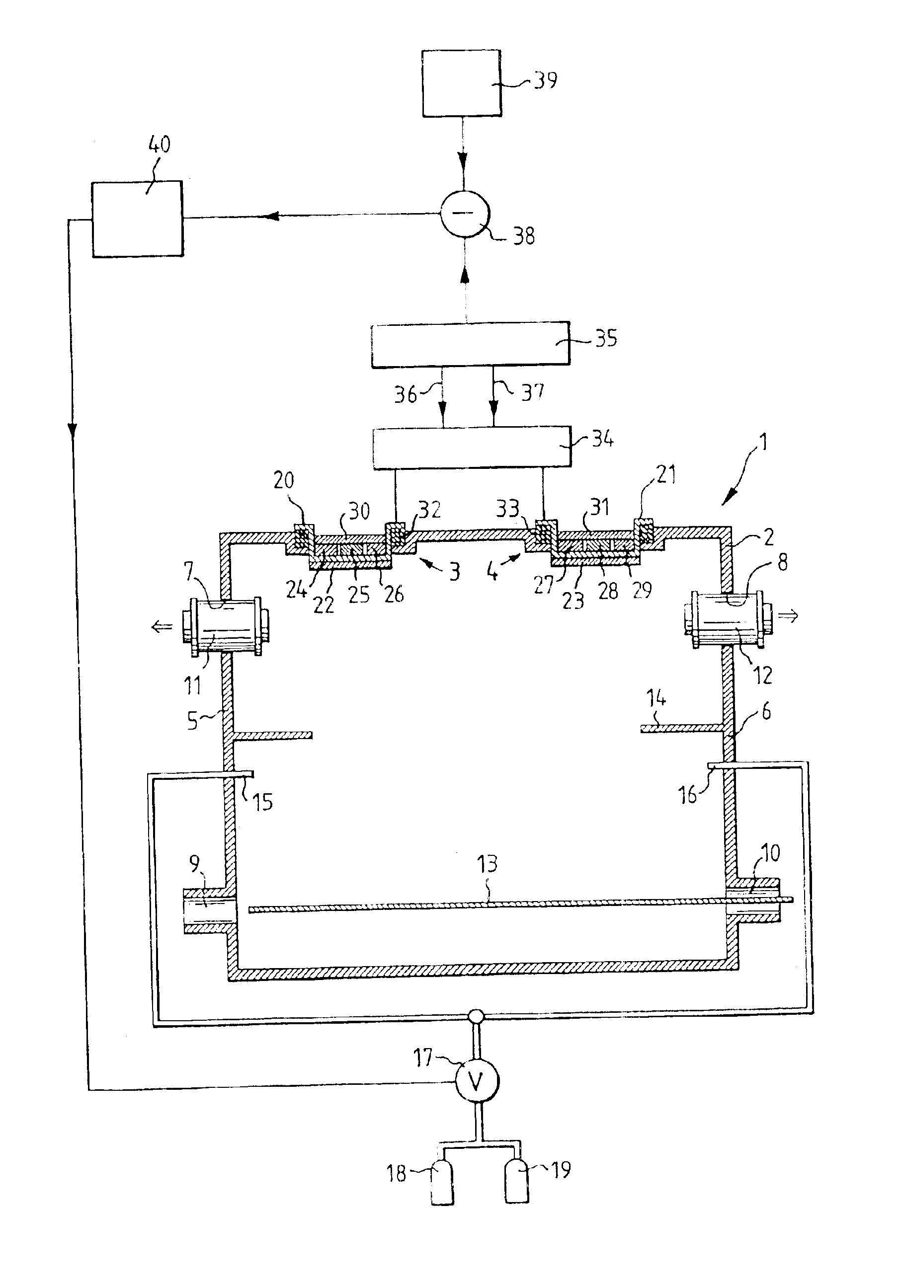
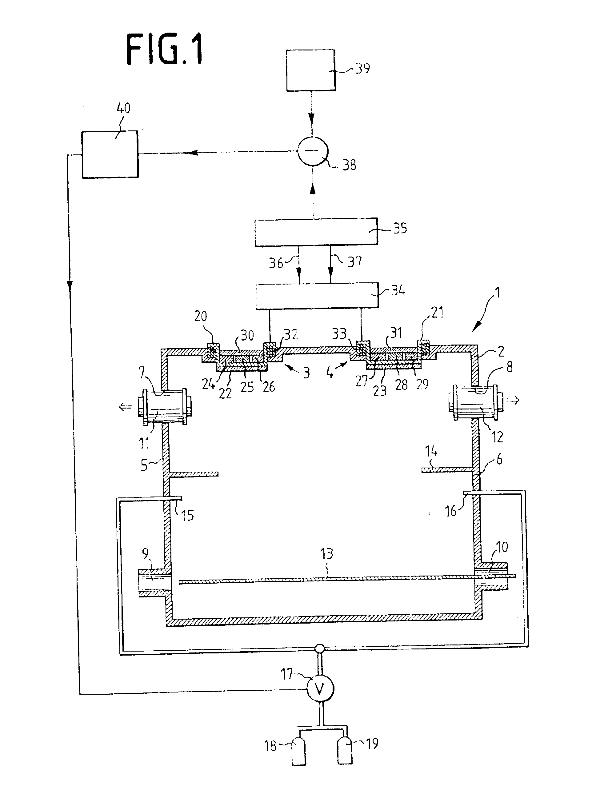
In FIG. 1 is depicted a sputter installation 1 which comprises a vacuum chamber 2 in which are disposed two magnetrons 3, 4. In side walls 5, 6 of the vacuum chamber 2 upper openings 7, 8 and lower openings 9, 10 are provided, and vacuum pumps 11, 12 are disposed in the upper openings 7, 8 while the lower openings 9, 10 serve for interlocking a substrate 13, for example a glass plate, through the vacuum chamber 2. Between the lower openings 9, 10 and the upper openings 7, 8 is disposed a mask 14 which projects from the side walls 5, 6 into the interior of the vacuum chamber 2. Beneath this mask 14 are located gas supply lines 15, 16 which are connected via a valve 17 with gas containers 18, 19.

Each magnetron 3, 4 comprises a cathode pan 20, 21, which is provided with a target 22, 23 on its underside. In the cathode pans 20, 21 are disposed in each instance three permanent magnets 24, 25, 26 or 27, 28, 29, respectively, with are connected with a common yoke 30, 31.

The cathode pans 20...


PUM

PropertyMeasurementUnit
impedanceaaaaaaaaaa
frequencyaaaaaaaaaa
frequencyaaaaaaaaaa

Abstract

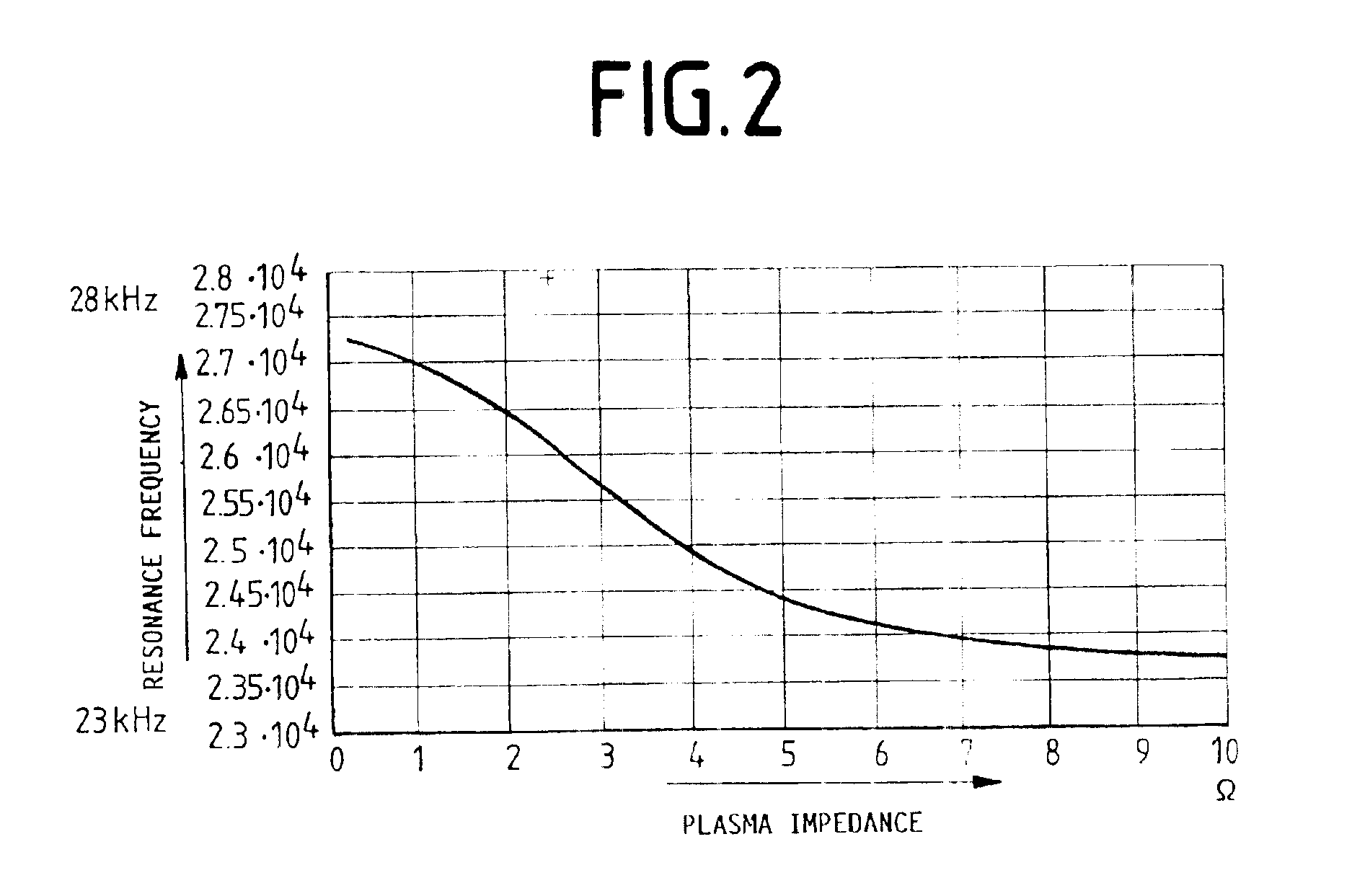
The invention relates to a device for the regulation of a plasma impedance in a vacuum chamber, wherein at least one electrode is connected to an AC generator. This AC generator is a free-running [oscillator], whose frequency adjusts to the resonance frequency of the load upon which it acts. This load comprises fixed circuit elements and a variable plasma impedance. If the plasma impedance is changed, with it the resonance frequency is also changed. The plasma impedance can thus be varied by acquisition of the resonance frequency and by presetting of a reference frequency value, for example thereby that the voltage, the current, the power or the gas inflow is varied as a function of the difference between resonance frequency and reference frequency value.

Description

FIELD OF THE INVENTIONThe invention relates to a device for the regulation of a plasma impedance.BACKGROUND AND SUMMARY OF THE INVENTIONFor the etching and vapor deposition of substrates very often the so-called sputter technique is employed, in which in a vacuum chamber at low pressure the ions of a gas are accelerated onto electrodes, where they knock out particles, which subsequently coat or etch a substrate. Acceleration of the gas ions takes place either by means of a DC or an AC voltage, which is applied to the substrate and to the electrodes.If an AC voltage is applied, the entire electric circuit comprises as a rule an AC voltage source, a network and a plasma impedance, i.e. of the impedance between the electrodes or between an electrode and the substrate, respectively. While the network as a rule has constant electric structural elements, which do not vary during operation, the plasma impedance can vary thereby that the fraction of ions and / or electrons varies relative to ...

Claims


Application Information

Patent Timeline
Patent Type & Authority Patents(United States)
IPC IPC(8): H01J37/32H01J37/34H05H1/46B01J3/00B01J19/08C23C14/34
CPCH01J37/32082H01J37/34H01J37/32935H01J37/32174
Inventor WILLMS, THOMASBRUCH, JURGEN
Owner APPLIED MATERIALS GMBH & CO KG
Learn More