Gap detection device for laser beam machine, laser beam machining system and gap detection method for laser beam machine

a laser beam machine and laser beam machining technology, applied in resistance/reactance/impedence, manufacturing tools, instruments, etc., can solve the problems of difficult to detect the gap between the nozzle and the work with high accuracy, and not completely eliminate the effect of plasma on detection

Inactive Publication Date: 2009-07-07
MITSUBISHI ELECTRIC CORP
View PDF27 Cites 2 Cited by
  • Summary
  • Abstract
  • Description
  • Claims
  • Application Information

AI Technical Summary

Benefits of technology

[0006]It is an object of the present invention to provide a technique to detect a gap between a nozzle of a laser beam machine for outputting a laser beam and an object to be machined with high accuracy.
[0010]In the present invention, since the gap between the nozzle and the object is obtained in consideration of not only the resistance component included in the plasma impedance but also the static capacitance component included it, it is possible to suppress the effect of the plasma generated during laser beam machining on detection of the gap. This makes it possible to detect the gap with high accuracy.

Problems solved by technology

Even if the frequency of the input signal to the sensor electrode is carefully selected, however, since the impedance due to the plasma slightly includes a static capacitance component as well as the resistance component, the technique of Japanese Patent Application Laid-Open No. 2000-234903 can not completely eliminate the effect of the plasma on detection of the gap.
Therefore, it is difficult to detect the gap between the nozzle and the work with high accuracy.

Method used


Image

  • Gap detection device for laser beam machine, laser beam machining system and gap detection method for laser beam machine
  • Gap detection device for laser beam machine, laser beam machining system and gap detection method for laser beam machine
  • Gap detection device for laser beam machine, laser beam machining system and gap detection method for laser beam machine

Examples


Embodiment Construction

The First Preferred Embodiment

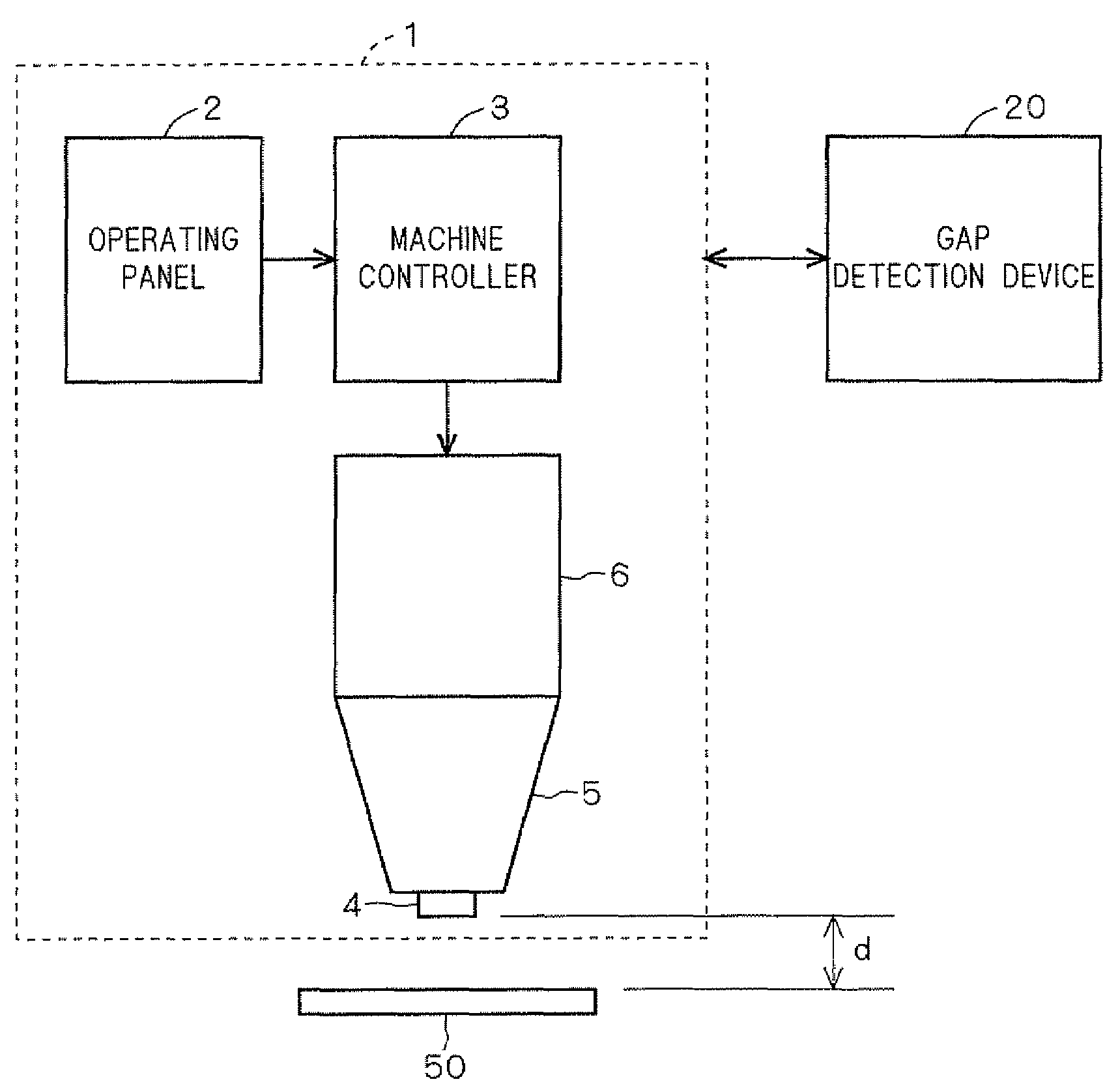
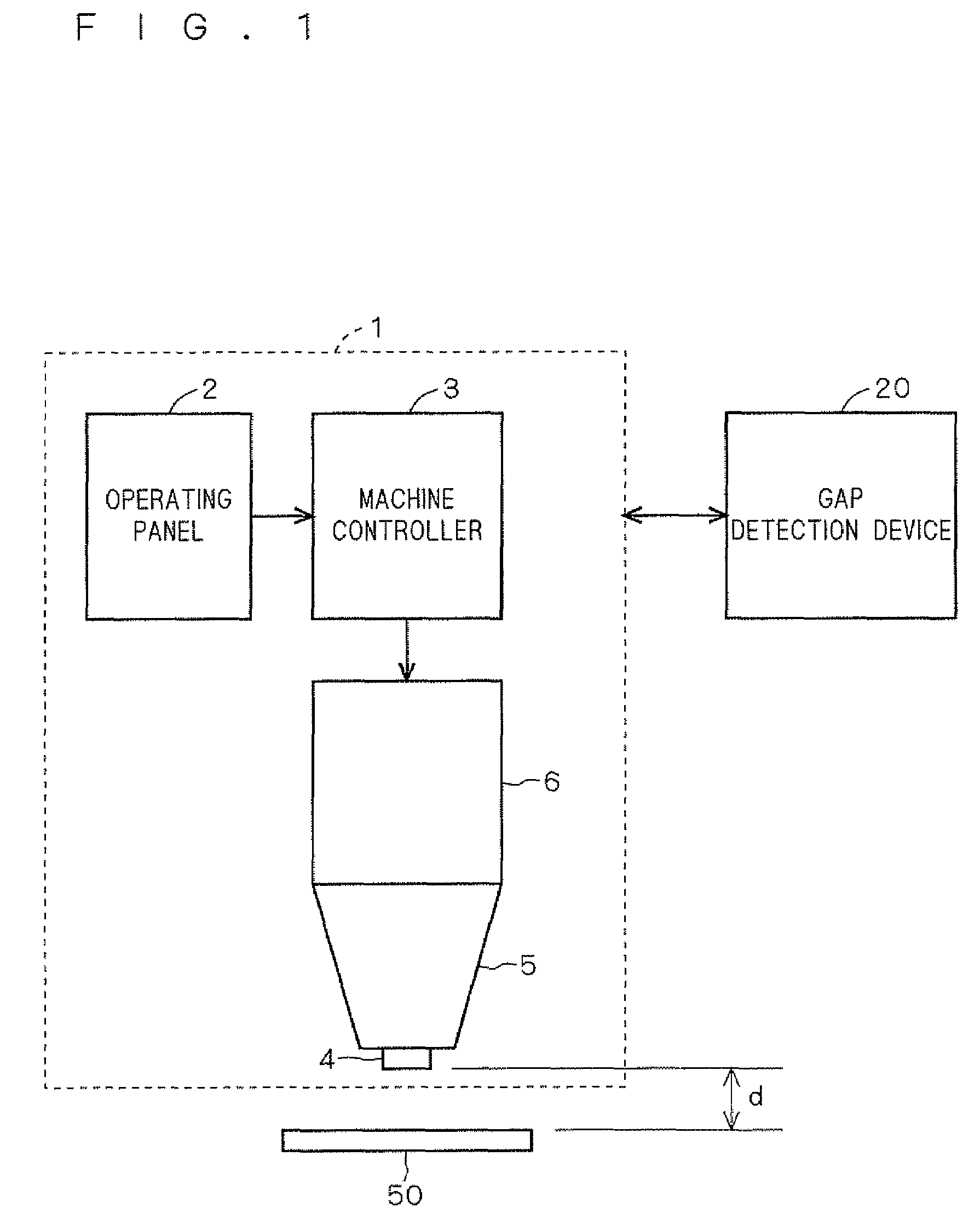
[0024]FIG. 1 is a view showing a constitution of a laser beam machining system in accordance with the first preferred embodiment of the present invention. As shown in FIG. 1, the laser beam machining system of the first preferred embodiment comprises a laser beam machine 1 for emitting a laser beam to a work 50, which is an object to be machined, such as a metal plate to machine the work 50 and a gap detection device 20 for measuring a gap d between a nozzle 4 of the laser beam machine 1, which will be described later, and the work 50.

[0025]The laser beam machine 1 comprises a operating panel 2 receiving an input of various information by a user. The user manipulates the operating panel 2 to input machining conditions such as a material or a thickness of the work 50 and the like to the laser beam machine 1. The laser beam machine 1 is provided with the nozzle 4 at a tip of a machining head 6, for outputting a laser beam, and provided with a guard electr...


PUM

PropertyMeasurementUnit
admittanceaaaaaaaaaa
impedanceaaaaaaaaaa
gap static capacitanceaaaaaaaaaa

Abstract

A signal processing portion obtains the reciprocal of a composite impedance of gap static capacitance and a plasma impedance, obtains composite static capacitance which is the sum of the gap static capacitance and a static capacitance component included in the plasma impedance from an imaginary part of the reciprocal, and obtains a resistance component included in the plasma impedance from a real part of the reciprocal. A gap detection device obtains the static capacitance component by using a model representing the characteristics of the reciprocal of the plasma impedance and the resistance component and obtains the gap static capacitance by subtracting the static capacitance component from the composite static capacitance. The gap detection device obtains a gap from the obtained gap static capacitance. Thus provided is a technique to detect a gap between a nozzle of a laser beam machine for outputting a laser beam and an object to be machined with high accuracy.

Description

BACKGROUND OF THE INVENTION[0001]1. Field of the Invention[0002]The present invention relates to a gap detection device for detecting a gap between a nozzle of a laser beam machine for outputting a laser beam and an object to be machined by using the laser beam, a gap detection method and a laser beam machining system.[0003]2. Description of the Background Art[0004]As to laser beam machining, various techniques have been proposed. Japanese Patent Application Laid-Open No. 2000-234903, for example, discloses a technique to detect a gap between a nozzle of a laser beam machine for outputting a laser beam and a work which is an object to be machined. Japanese Patent Application Laid-Open No. 4-356391(1992) discloses a technique to ensure stabilization of static capacitance between a nozzle and a work by reducing plasma generated during laser beam machining.[0005]In the above Japanese Patent Application Laid-Open No. 2000-234903, the frequency of an input signal to a sensor electrode is...

Claims


Application Information

Patent Timeline
Patent Type & Authority Patents(United States)
IPC IPC(8): G01R27/26B23K9/00B23K9/06B23K26/00G01B7/14
CPCB23K26/04
Inventor IWATA, TAKAAKIOMURA, HIROYOSHIIMAI, YOSHIHITOTAKAHASHI, TEIJI
Owner MITSUBISHI ELECTRIC CORP
Why Eureka
Try Eureka